 GitBucket
ARM Trusted Firmware Design
Contents :
- Introduction
- Cold boot
- EL3 runtime services framework
- Power State Coordination Interface
- Secure-EL1 Payloads and Dispatchers
- Crash Reporting in BL3-1
- Guidelines for Reset Handlers
- CPU specific operations framework
- Memory layout of BL images
- Firmware Image Package (FIP)
- Use of coherent memory in Trusted Firmware
- Code Structure
- References
1. Introduction
The ARM Trusted Firmware implements a subset of the Trusted Board Boot Requirements (TBBR) Platform Design Document (PDD) [1] for ARM reference platforms. The TBB sequence starts when the platform is powered on and runs up to the stage where it hands-off control to firmware running in the normal world in DRAM. This is the cold boot path.
The ARM Trusted Firmware also implements the Power State Coordination Interface (PSCI) PDD [2] as a runtime service. PSCI is the interface from normal world software to firmware implementing power management use-cases (for example, secondary CPU boot, hotplug and idle). Normal world software can access ARM Trusted Firmware runtime services via the ARM SMC (Secure Monitor Call) instruction. The SMC instruction must be used as mandated by the SMC Calling Convention PDD [3].
The ARM Trusted Firmware implements a framework for configuring and managing interrupts generated in either security state. The details of the interrupt management framework and its design can be found in ARM Trusted Firmware Interrupt Management Design guide [4].
2. Cold boot
The cold boot path starts when the platform is physically turned on. One of the CPUs released from reset is chosen as the primary CPU, and the remaining CPUs are considered secondary CPUs. The primary CPU is chosen through platform-specific means. The cold boot path is mainly executed by the primary CPU, other than essential CPU initialization executed by all CPUs. The secondary CPUs are kept in a safe platform-specific state until the primary CPU has performed enough initialization to boot them.
The cold boot path in this implementation of the ARM Trusted Firmware is divided into five steps (in order of execution):
- Boot Loader stage 1 (BL1) AP Trusted ROM
- Boot Loader stage 2 (BL2) Trusted Boot Firmware
- Boot Loader stage 3-1 (BL3-1) EL3 Runtime Firmware
- Boot Loader stage 3-2 (BL3-2) Secure-EL1 Payload (optional)
- Boot Loader stage 3-3 (BL3-3) Non-trusted Firmware
ARM development platforms (Fixed Virtual Platforms (FVPs) and Juno) implement a combination of the following types of memory regions. Each bootloader stage uses one or more of these memory regions.
- Regions accessible from both non-secure and secure states. For example, non-trusted SRAM, ROM and DRAM.
- Regions accessible from only the secure state. For example, trusted SRAM and ROM. The FVPs also implement the trusted DRAM which is statically configured. Additionally, the Base FVPs and Juno development platform configure the TrustZone Controller (TZC) to create a region in the DRAM which is accessible only from the secure state.
The sections below provide the following details:
- initialization and execution of the first three stages during cold boot
- specification of the BL3-1 entrypoint requirements for use by alternative Trusted Boot Firmware in place of the provided BL1 and BL2
- changes in BL3-1 behavior when using the
RESET_TO_BL31option which allows BL3-1 to run without BL1 and BL2
BL1
This stage begins execution from the platform's reset vector at EL3. The reset address is platform dependent but it is usually located in a Trusted ROM area. The BL1 data section is copied to trusted SRAM at runtime.
On the ARM development platforms, BL1 code starts execution from the reset vector defined by the constant BL1_RO_BASE. The BL1 data section is copied to the top of trusted SRAM as defined by the constant BL1_RW_BASE.
The functionality implemented by this stage is as follows.
Determination of boot path
Whenever a CPU is released from reset, BL1 needs to distinguish between a warm boot and a cold boot. This is done using platform-specific mechanisms (see the platform_get_entrypoint() function in the [Porting Guide]). In the case of a warm boot, a CPU is expected to continue execution from a seperate entrypoint. In the case of a cold boot, the secondary CPUs are placed in a safe platform-specific state (see the plat_secondary_cold_boot_setup() function in the [Porting Guide]) while the primary CPU executes the remaining cold boot path as described in the following sections.
Architectural initialization
BL1 performs minimal architectural initialization as follows.
-
Exception vectors
BL1 sets up simple exception vectors for both synchronous and asynchronous exceptions. The default behavior upon receiving an exception is to populate a status code in the general purpose register
X0and call theplat_report_exception()function (see the [Porting Guide]). The status code is one of:0x0 : Synchronous exception from Current EL with SP_EL0 0x1 : IRQ exception from Current EL with SP_EL0 0x2 : FIQ exception from Current EL with SP_EL0 0x3 : System Error exception from Current EL with SP_EL0 0x4 : Synchronous exception from Current EL with SP_ELx 0x5 : IRQ exception from Current EL with SP_ELx 0x6 : FIQ exception from Current EL with SP_ELx 0x7 : System Error exception from Current EL with SP_ELx 0x8 : Synchronous exception from Lower EL using aarch64 0x9 : IRQ exception from Lower EL using aarch64 0xa : FIQ exception from Lower EL using aarch64 0xb : System Error exception from Lower EL using aarch64 0xc : Synchronous exception from Lower EL using aarch32 0xd : IRQ exception from Lower EL using aarch32 0xe : FIQ exception from Lower EL using aarch32 0xf : System Error exception from Lower EL using aarch32
The
plat_report_exception()implementation on the ARM FVP port programs the Versatile Express System LED register in the following format to indicate the occurence of an unexpected exception:SYS_LED[0] - Security state (Secure=0/Non-Secure=1) SYS_LED[2:1] - Exception Level (EL3=0x3, EL2=0x2, EL1=0x1, EL0=0x0) SYS_LED[7:3] - Exception Class (Sync/Async & origin). This is the value of the status codeA write to the LED register reflects in the System LEDs (S6LED0..7) in the CLCD window of the FVP.
BL1 does not expect to receive any exceptions other than the SMC exception. For the latter, BL1 installs a simple stub. The stub expects to receive only a single type of SMC (determined by its function ID in the general purpose register
X0). This SMC is raised by BL2 to make BL1 pass control to BL3-1 (loaded by BL2) at EL3. Any other SMC leads to an assertion failure. -
CPU initialization
BL1 calls the
reset_handler()function which in turn calls the CPU specific reset handler function (see the section: "CPU specific operations framework"). -
MMU setup
BL1 sets up EL3 memory translation by creating page tables to cover the first 4GB of physical address space. This covers all the memories and peripherals needed by BL1.
-
Control register setup
-
SCTLR_EL3. Instruction cache is enabled by setting theSCTLR_EL3.Ibit. Alignment and stack alignment checking is enabled by setting theSCTLR_EL3.AandSCTLR_EL3.SAbits. Exception endianness is set to little-endian by clearing theSCTLR_EL3.EEbit. -
SCR_EL3. The register width of the next lower exception level is set to AArch64 by setting theSCR.RWbit. -
CPTR_EL3. Accesses to theCPACR_EL1register from EL1 or EL2, or theCPTR_EL2register from EL2 are configured to not trap to EL3 by clearing theCPTR_EL3.TCPACbit. Access to the trace functionality is configured not to trap to EL3 by clearing theCPTR_EL3.TTAbit. Instructions that access the registers associated with Floating Point and Advanced SIMD execution are configured to not trap to EL3 by clearing theCPTR_EL3.TFPbit.
-
Platform initialization
BL1 enables issuing of snoop and DVM (Distributed Virtual Memory) requests to the CCI slave interface corresponding to the cluster that includes the primary CPU. BL1 also initializes a UART (PL011 console), which enables access to the printf family of functions in BL1.
BL2 image load and execution
BL1 execution continues as follows:
-
BL1 determines the amount of free trusted SRAM memory available by calculating the extent of its own data section, which also resides in trusted SRAM. BL1 loads a BL2 raw binary image from platform storage, at a platform-specific base address. If the BL2 image file is not present or if there is not enough free trusted SRAM the following error message is printed:
"Failed to load boot loader stage 2 (BL2) firmware."
If the load is successful, BL1 updates the limits of the remaining free trusted SRAM. It also populates information about the amount of trusted SRAM used by the BL2 image. The exact load location of the image is provided as a base address in the platform header. Further description of the memory layout can be found later in this document.
-
BL1 prints the following string from the primary CPU to indicate successful execution of the BL1 stage:
"Booting trusted firmware boot loader stage 1"
-
BL1 passes control to the BL2 image at Secure EL1, starting from its load address.
-
BL1 also passes information about the amount of trusted SRAM used and available for use. This information is populated at a platform-specific memory address.
BL2
BL1 loads and passes control to BL2 at Secure-EL1. BL2 is linked against and loaded at a platform-specific base address (more information can be found later in this document). The functionality implemented by BL2 is as follows.
Architectural initialization
BL2 performs minimal architectural initialization required for subsequent stages of the ARM Trusted Firmware and normal world software. It sets up Secure EL1 memory translation by creating page tables to address the first 4GB of the physical address space in a similar way to BL1. EL1 and EL0 are given access to Floating Point & Advanced SIMD registers by clearing the CPACR.FPEN bits.
Platform initialization
BL2 copies the information regarding the trusted SRAM populated by BL1 using a platform-specific mechanism. It calculates the limits of DRAM (main memory) to determine whether there is enough space to load the BL3-3 image. A platform defined base address is used to specify the load address for the BL3-1 image. It also defines the extents of memory available for use by the BL3-2 image. BL2 also initializes a UART (PL011 console), which enables access to the printf family of functions in BL2. Platform security is initialized to allow access to controlled components. The storage abstraction layer is initialized which is used to load further bootloader images.
SCP_BL2 (System Control Processor Firmware) image load
Some systems have a separate System Control Processor (SCP) for power, clock, reset and system control. BL2 loads the optional SCP_BL2 image from platform storage into a platform-specific region of secure memory. The subsequent handling of SCP_BL2 is platform specific. For example, on the Juno ARM development platform port the image is transferred into SCP's internal memory using the Boot Over MHU (BOM) protocol after being loaded in the trusted SRAM memory. The SCP executes SCP_BL2 and signals to the Application Processor (AP) for BL2 execution to continue.
BL3-1 (EL3 Runtime Firmware) image load
BL2 loads the BL3-1 image from platform storage into a platform-specific address in trusted SRAM. If there is not enough memory to load the image or image is missing it leads to an assertion failure. If the BL3-1 image loads successfully, BL2 updates the amount of trusted SRAM used and available for use by BL3-1. This information is populated at a platform-specific memory address.
BL3-2 (Secure-EL1 Payload) image load
BL2 loads the optional BL3-2 image from platform storage into a platform- specific region of secure memory. The image executes in the secure world. BL2 relies on BL3-1 to pass control to the BL3-2 image, if present. Hence, BL2 populates a platform-specific area of memory with the entrypoint/load-address of the BL3-2 image. The value of the Saved Processor Status Register (SPSR) for entry into BL3-2 is not determined by BL2, it is initialized by the Secure-EL1 Payload Dispatcher (see later) within BL3-1, which is responsible for managing interaction with BL3-2. This information is passed to BL3-1.
BL3-3 (Non-trusted Firmware) image load
BL2 loads the BL3-3 image (e.g. UEFI or other test or boot software) from platform storage into non-secure memory as defined by the platform.
BL2 relies on BL3-1 to pass control to BL3-3 once secure state initialization is complete. Hence, BL2 populates a platform-specific area of memory with the entrypoint and Saved Program Status Register (SPSR) of the normal world software image. The entrypoint is the load address of the BL3-3 image. The SPSR is determined as specified in Section 5.13 of the PSCI PDD. This information is passed to BL3-1.
BL3-1 (EL3 Runtime Firmware) execution
BL2 execution continues as follows:
-
BL2 passes control back to BL1 by raising an SMC, providing BL1 with the BL3-1 entrypoint. The exception is handled by the SMC exception handler installed by BL1.
-
BL1 turns off the MMU and flushes the caches. It clears the
SCTLR_EL3.M/I/Cbits, flushes the data cache to the point of coherency and invalidates the TLBs. -
BL1 passes control to BL3-1 at the specified entrypoint at EL3.
BL3-1
The image for this stage is loaded by BL2 and BL1 passes control to BL3-1 at EL3. BL3-1 executes solely in trusted SRAM. BL3-1 is linked against and loaded at a platform-specific base address (more information can be found later in this document). The functionality implemented by BL3-1 is as follows.
Architectural initialization
Currently, BL3-1 performs a similar architectural initialization to BL1 as far as system register settings are concerned. Since BL1 code resides in ROM, architectural initialization in BL3-1 allows override of any previous initialization done by BL1. BL3-1 creates page tables to address the first 4GB of physical address space and initializes the MMU accordingly. It initializes a buffer of frequently used pointers, called per-CPU pointer cache, in memory for faster access. Currently the per-CPU pointer cache contains only the pointer to crash stack. It then replaces the exception vectors populated by BL1 with its own. BL3-1 exception vectors implement more elaborate support for handling SMCs since this is the only mechanism to access the runtime services implemented by BL3-1 (PSCI for example). BL3-1 checks each SMC for validity as specified by the SMC calling convention PDD before passing control to the required SMC handler routine. BL3-1 programs the CNTFRQ_EL0 register with the clock frequency of the system counter, which is provided by the platform.
Platform initialization
BL3-1 performs detailed platform initialization, which enables normal world software to function correctly. It also retrieves entrypoint information for the BL3-3 image loaded by BL2 from the platform defined memory address populated by BL2. It enables issuing of snoop and DVM (Distributed Virtual Memory) requests to the CCI slave interface corresponding to the cluster that includes the primary CPU. BL3-1 also initializes a UART (PL011 console), which enables access to the printf family of functions in BL3-1. It enables the system level implementation of the generic timer through the memory mapped interface.
-
GICv2 initialization:
- Enable group0 interrupts in the GIC CPU interface.
- Configure group0 interrupts to be asserted as FIQs.
- Disable the legacy interrupt bypass mechanism.
- Configure the priority mask register to allow interrupts of all priorities to be signaled to the CPU interface.
- Mark SGIs 8-15 and the other secure interrupts on the platform as group0 (secure).
- Target all secure SPIs to CPU0.
- Enable these group0 interrupts in the GIC distributor.
- Configure all other interrupts as group1 (non-secure).
- Enable signaling of group0 interrupts in the GIC distributor.
-
GICv3 initialization:
If a GICv3 implementation is available in the platform, BL3-1 initializes the GICv3 in GICv2 emulation mode with settings as described for GICv2 above.
-
Power management initialization:
BL3-1 implements a state machine to track CPU and cluster state. The state can be one of
OFF,ON_PENDING,SUSPENDorON. All secondary CPUs are initially in theOFFstate. The cluster that the primary CPU belongs to isON; any other cluster isOFF. BL3-1 initializes the data structures that implement the state machine, including the locks that protect them. BL3-1 accesses the state of a CPU or cluster immediately after reset and before the data cache is enabled in the warm boot path. It is not currently possible to use 'exclusive' based spinlocks, therefore BL3-1 uses locks based on Lamport's Bakery algorithm instead. BL3-1 allocates these locks in device memory by default. -
Runtime services initialization:
The runtime service framework and its initialization is described in the "EL3 runtime services framework" section below.
Details about the PSCI service are provided in the "Power State Coordination Interface" section below.
-
BL3-2 (Secure-EL1 Payload) image initialization
If a BL3-2 image is present then there must be a matching Secure-EL1 Payload Dispatcher (SPD) service (see later for details). During initialization that service must register a function to carry out initialization of BL3-2 once the runtime services are fully initialized. BL3-1 invokes such a registered function to initialize BL3-2 before running BL3-3.
Details on BL3-2 initialization and the SPD's role are described in the "Secure-EL1 Payloads and Dispatchers" section below.
-
BL3-3 (Non-trusted Firmware) execution
BL3-1 initializes the EL2 or EL1 processor context for normal-world cold boot, ensuring that no secure state information finds its way into the non-secure execution state. BL3-1 uses the entrypoint information provided by BL2 to jump to the Non-trusted firmware image (BL3-3) at the highest available Exception Level (EL2 if available, otherwise EL1).
Using alternative Trusted Boot Firmware in place of BL1 and BL2
Some platforms have existing implementations of Trusted Boot Firmware that would like to use ARM Trusted Firmware BL3-1 for the EL3 Runtime Firmware. To enable this firmware architecture it is important to provide a fully documented and stable interface between the Trusted Boot Firmware and BL3-1.
Future changes to the BL3-1 interface will be done in a backwards compatible way, and this enables these firmware components to be independently enhanced/ updated to develop and exploit new functionality.
Required CPU state when calling bl31_entrypoint() during cold boot
This function must only be called by the primary CPU.
On entry to this function the calling primary CPU must be executing in AArch64 EL3, little-endian data access, and all interrupt sources masked:
PSTATE.EL = 3
PSTATE.RW = 1
PSTATE.DAIF = 0xf
SCTLR_EL3.EE = 0
X0 and X1 can be used to pass information from the Trusted Boot Firmware to the platform code in BL3-1:
X0 : Reserved for common Trusted Firmware information
X1 : Platform specific information
BL3-1 zero-init sections (e.g. .bss) should not contain valid data on entry, these will be zero filled prior to invoking platform setup code.
Use of the X0 and X1 parameters
The parameters are platform specific and passed from bl31_entrypoint() to bl31_early_platform_setup(). The value of these parameters is never directly used by the common BL3-1 code.
The convention is that X0 conveys information regarding the BL3-1, BL3-2 and BL3-3 images from the Trusted Boot firmware and X1 can be used for other platform specific purpose. This convention allows platforms which use ARM Trusted Firmware's BL1 and BL2 images to transfer additional platform specific information from Secure Boot without conflicting with future evolution of the Trusted Firmware using X0 to pass a bl31_params structure.
BL3-1 common and SPD initialization code depends on image and entrypoint information about BL3-3 and BL3-2, which is provided via BL3-1 platform APIs. This information is required until the start of execution of BL3-3. This information can be provided in a platform defined manner, e.g. compiled into the platform code in BL3-1, or provided in a platform defined memory location by the Trusted Boot firmware, or passed from the Trusted Boot Firmware via the Cold boot Initialization parameters. This data may need to be cleaned out of the CPU caches if it is provided by an earlier boot stage and then accessed by BL3-1 platform code before the caches are enabled.
ARM Trusted Firmware's BL2 implementation passes a bl31_params structure in X0 and the ARM development platforms interpret this in the BL3-1 platform code.
MMU, Data caches & Coherency
BL3-1 does not depend on the enabled state of the MMU, data caches or interconnect coherency on entry to bl31_entrypoint(). If these are disabled on entry, these should be enabled during bl31_plat_arch_setup().
Data structures used in the BL3-1 cold boot interface
These structures are designed to support compatibility and independent evolution of the structures and the firmware images. For example, a version of BL3-1 that can interpret the BL3-x image information from different versions of BL2, a platform that uses an extended entry_point_info structure to convey additional register information to BL3-1, or a ELF image loader that can convey more details about the firmware images.
To support these scenarios the structures are versioned and sized, which enables BL3-1 to detect which information is present and respond appropriately. The param_header is defined to capture this information:
typedef struct param_header {
    uint8_t type;       /* type of the structure */
    uint8_t version;    /* version of this structure */
    uint16_t size;      /* size of this structure in bytes */
    uint32_t attr;      /* attributes: unused bits SBZ */
} param_header_t;
The structures using this format are entry_point_info, image_info and bl31_params. The code that allocates and populates these structures must set the header fields appropriately, and the SET_PARAM_HEAD() a macro is defined to simplify this action.
Required CPU state for BL3-1 Warm boot initialization
When requesting a CPU power-on, or suspending a running CPU, ARM Trusted Firmware provides the platform power management code with a Warm boot initialization entry-point, to be invoked by the CPU immediately after the reset handler. On entry to the Warm boot initialization function the calling CPU must be in AArch64 EL3, little-endian data access and all interrupt sources masked:
PSTATE.EL = 3
PSTATE.RW = 1
PSTATE.DAIF = 0xf
SCTLR_EL3.EE = 0
The PSCI implementation will initialize the processor state and ensure that the platform power management code is then invoked as required to initialize all necessary system, cluster and CPU resources.
Using BL3-1 as the CPU reset vector
On some platforms the runtime firmware (BL3-x images) for the application processors are loaded by trusted firmware running on a secure system processor on the SoC, rather than by BL1 and BL2 running on the primary application processor. For this type of SoC it is desirable for the application processor to always reset to BL3-1 which eliminates the need for BL1 and BL2.
ARM Trusted Firmware provides a build-time option RESET_TO_BL31 that includes some additional logic in the BL3-1 entrypoint to support this use case.
In this configuration, the platform's Trusted Boot Firmware must ensure that BL3-1 is loaded to its runtime address, which must match the CPU's RVBAR reset vector address, before the application processor is powered on. Additionally, platform software is responsible for loading the other BL3-x images required and providing entry point information for them to BL3-1. Loading these images might be done by the Trusted Boot Firmware or by platform code in BL3-1.
The ARM FVP port supports the RESET_TO_BL31 configuration, in which case the bl31.bin image must be loaded to its run address in Trusted SRAM and all CPU reset vectors be changed from the default 0x0 to this run address. See the [User Guide] for details of running the FVP models in this way.
This configuration requires some additions and changes in the BL3-1 functionality:
Determination of boot path
In this configuration, BL3-1 uses the same reset framework and code as the one described for BL1 above. On a warm boot a CPU is directed to the PSCI implementation via a platform defined mechanism. On a cold boot, the platform must place any secondary CPUs into a safe state while the primary CPU executes a modified BL3-1 initialization, as described below.
Platform initialization
In this configuration, when the CPU resets to BL3-1 there are no parameters that can be passed in registers by previous boot stages. Instead, the platform code in BL3-1 needs to know, or be able to determine, the location of the BL3-2 (if required) and BL3-3 images and provide this information in response to the bl31_plat_get_next_image_ep_info() function.
As the first image to execute in this configuration BL3-1 must also ensure that any security initialisation, for example programming a TrustZone address space controller, is carried out during early platform initialisation.
3. EL3 runtime services framework
Software executing in the non-secure state and in the secure state at exception levels lower than EL3 will request runtime services using the Secure Monitor Call (SMC) instruction. These requests will follow the convention described in the SMC Calling Convention PDD (SMCCC). The SMCCC assigns function identifiers to each SMC request and describes how arguments are passed and returned.
The EL3 runtime services framework enables the development of services by different providers that can be easily integrated into final product firmware. The following sections describe the framework which facilitates the registration, initialization and use of runtime services in EL3 Runtime Firmware (BL3-1).
The design of the runtime services depends heavily on the concepts and definitions described in the SMCCC, in particular SMC Function IDs, Owning Entity Numbers (OEN), Fast and Standard calls, and the SMC32 and SMC64 calling conventions. Please refer to that document for more detailed explanation of these terms.
The following runtime services are expected to be implemented first. They have not all been instantiated in the current implementation.
-
Standard service calls
This service is for management of the entire system. The Power State Coordination Interface (PSCI) is the first set of standard service calls defined by ARM (see PSCI section later).
NOTE: Currently this service is called PSCI since there are no other defined standard service calls.
-
Secure-EL1 Payload Dispatcher service
If a system runs a Trusted OS or other Secure-EL1 Payload (SP) then it also requires a Secure Monitor at EL3 to switch the EL1 processor context between the normal world (EL1/EL2) and trusted world (Secure-EL1). The Secure Monitor will make these world switches in response to SMCs. The SMCCC provides for such SMCs with the Trusted OS Call and Trusted Application Call OEN ranges.
The interface between the EL3 Runtime Firmware and the Secure-EL1 Payload is not defined by the SMCCC or any other standard. As a result, each Secure-EL1 Payload requires a specific Secure Monitor that runs as a runtime service - within ARM Trusted Firmware this service is referred to as the Secure-EL1 Payload Dispatcher (SPD).
ARM Trusted Firmware provides a Test Secure-EL1 Payload (TSP) and its associated Dispatcher (TSPD). Details of SPD design and TSP/TSPD operation are described in the "Secure-EL1 Payloads and Dispatchers" section below.
-
CPU implementation service
This service will provide an interface to CPU implementation specific services for a given platform e.g. access to processor errata workarounds. This service is currently unimplemented.
Additional services for ARM Architecture, SiP and OEM calls can be implemented. Each implemented service handles a range of SMC function identifiers as described in the SMCCC.
Registration
A runtime service is registered using the DECLARE_RT_SVC() macro, specifying the name of the service, the range of OENs covered, the type of service and initialization and call handler functions. This macro instantiates a const struct rt_svc_desc for the service with these details (see runtime_svc.h). This structure is allocated in a special ELF section rt_svc_descs, enabling the framework to find all service descriptors included into BL3-1.
The specific service for a SMC Function is selected based on the OEN and call type of the Function ID, and the framework uses that information in the service descriptor to identify the handler for the SMC Call.
The service descriptors do not include information to identify the precise set of SMC function identifiers supported by this service implementation, the security state from which such calls are valid nor the capability to support 64-bit and/or 32-bit callers (using SMC32 or SMC64). Responding appropriately to these aspects of a SMC call is the responsibility of the service implementation, the framework is focused on integration of services from different providers and minimizing the time taken by the framework before the service handler is invoked.
Details of the parameters, requirements and behavior of the initialization and call handling functions are provided in the following sections.
Initialization
runtime_svc_init() in runtime_svc.c initializes the runtime services framework running on the primary CPU during cold boot as part of the BL3-1 initialization. This happens prior to initializing a Trusted OS and running Normal world boot firmware that might in turn use these services. Initialization involves validating each of the declared runtime service descriptors, calling the service initialization function and populating the index used for runtime lookup of the service.
The BL3-1 linker script collects all of the declared service descriptors into a single array and defines symbols that allow the framework to locate and traverse the array, and determine its size.
The framework does basic validation of each descriptor to halt firmware initialization if service declaration errors are detected. The framework does not check descriptors for the following error conditions, and may behave in an unpredictable manner under such scenarios:
- Overlapping OEN ranges
- Multiple descriptors for the same range of OENs and
call_type - Incorrect range of owning entity numbers for a given
call_type
Once validated, the service init() callback is invoked. This function carries out any essential EL3 initialization before servicing requests. The init() function is only invoked on the primary CPU during cold boot. If the service uses per-CPU data this must either be initialized for all CPUs during this call, or be done lazily when a CPU first issues an SMC call to that service. If init() returns anything other than 0, this is treated as an initialization error and the service is ignored: this does not cause the firmware to halt.
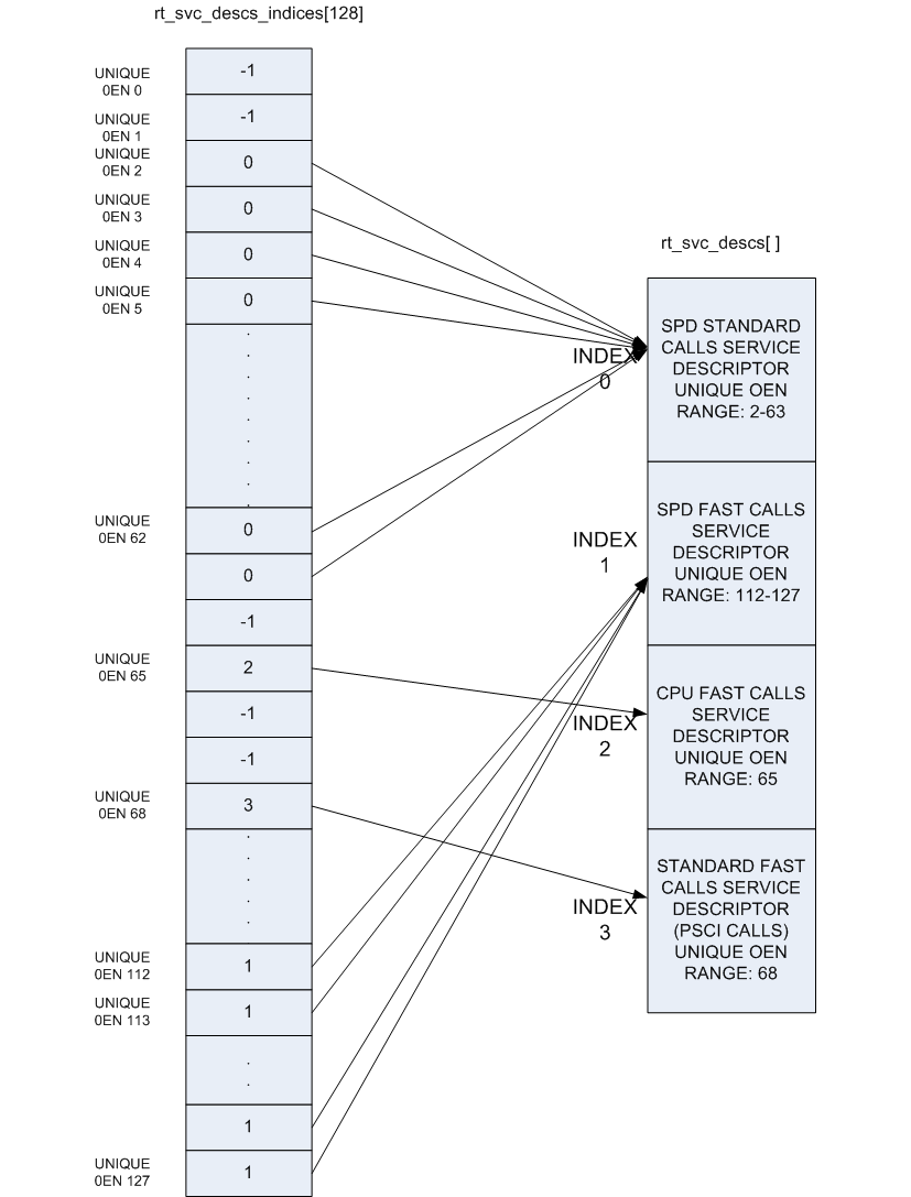
The OEN and call type fields present in the SMC Function ID cover a total of 128 distinct services, but in practice a single descriptor can cover a range of OENs, e.g. SMCs to call a Trusted OS function. To optimize the lookup of a service handler, the framework uses an array of 128 indices that map every distinct OEN/call-type combination either to one of the declared services or to indicate the service is not handled. This rt_svc_descs_indices[] array is populated for all of the OENs covered by a service after the service init() function has reported success. So a service that fails to initialize will never have it's handle() function invoked.
The following figure shows how the rt_svc_descs_indices[] index maps the SMC Function ID call type and OEN onto a specific service handler in the rt_svc_descs[] array.
Handling an SMC
When the EL3 runtime services framework receives a Secure Monitor Call, the SMC Function ID is passed in W0 from the lower exception level (as per the SMCCC). If the calling register width is AArch32, it is invalid to invoke an SMC Function which indicates the SMC64 calling convention: such calls are ignored and return the Unknown SMC Function Identifier result code 0xFFFFFFFF in R0/X0.
Bit[31] (fast/standard call) and bits[29:24] (owning entity number) of the SMC Function ID are combined to index into the rt_svc_descs_indices[] array. The resulting value might indicate a service that has no handler, in this case the framework will also report an Unknown SMC Function ID. Otherwise, the value is used as a further index into the rt_svc_descs[] array to locate the required service and handler.
The service's handle() callback is provided with five of the SMC parameters directly, the others are saved into memory for retrieval (if needed) by the handler. The handler is also provided with an opaque handle for use with the supporting library for parameter retrieval, setting return values and context manipulation; and with flags indicating the security state of the caller. The framework finally sets up the execution stack for the handler, and invokes the services handle() function.
On return from the handler the result registers are populated in X0-X3 before restoring the stack and CPU state and returning from the original SMC.
4. Power State Coordination Interface
TODO: Provide design walkthrough of PSCI implementation.
The PSCI v1.0 specification categorizes APIs as optional and mandatory. All the mandatory APIs in PSCI v1.0 and all the APIs in PSCI v0.2 draft specification Power State Coordination Interface PDD are implemented. The table lists the PSCI v1.0 APIs and their support in generic code.
An API implementation might have a dependency on platform code e.g. CPU_SUSPEND requires the platform to export a part of the implementation. Hence the level of support of the mandatory APIs depends upon the support exported by the platform port as well. The Juno and FVP (all variants) platforms export all the required support.
| PSCI v1.0 API | Supported | Comments |
|---|---|---|
PSCI_VERSION |
Yes | The version returned is 1.0 |
CPU_SUSPEND |
Yes* | The original power_state format is used |
CPU_OFF |
Yes* | |
CPU_ON |
Yes* | |
AFFINITY_INFO |
Yes | |
MIGRATE |
Yes** | |
MIGRATE_INFO_TYPE |
Yes** | |
MIGRATE_INFO_CPU |
Yes** | |
SYSTEM_OFF |
Yes* | |
SYSTEM_RESET |
Yes* | |
PSCI_FEATURES |
Yes | |
CPU_FREEZE |
No | |
CPU_DEFAULT_SUSPEND |
No | |
CPU_HW_STATE |
No | |
SYSTEM_SUSPEND |
Yes* | |
PSCI_SET_SUSPEND_MODE |
No | |
PSCI_STAT_RESIDENCY |
No | |
PSCI_STAT_COUNT |
No |
*Note : These PSCI APIs require platform power management hooks to be registered with the generic PSCI code to be supported.
**Note : These PSCI APIs require appropriate Secure Payload Dispatcher hooks to be registered with the generic PSCI code to be supported.
5. Secure-EL1 Payloads and Dispatchers
On a production system that includes a Trusted OS running in Secure-EL1/EL0, the Trusted OS is coupled with a companion runtime service in the BL3-1 firmware. This service is responsible for the initialisation of the Trusted OS and all communications with it. The Trusted OS is the BL3-2 stage of the boot flow in ARM Trusted Firmware. The firmware will attempt to locate, load and execute a BL3-2 image.
ARM Trusted Firmware uses a more general term for the BL3-2 software that runs at Secure-EL1 - the Secure-EL1 Payload - as it is not always a Trusted OS.
The ARM Trusted Firmware provides a Test Secure-EL1 Payload (TSP) and a Test Secure-EL1 Payload Dispatcher (TSPD) service as an example of how a Trusted OS is supported on a production system using the Runtime Services Framework. On such a system, the Test BL3-2 image and service are replaced by the Trusted OS and its dispatcher service. The ARM Trusted Firmware build system expects that the dispatcher will define the build flag NEED_BL32 to enable it to include the BL3-2 in the build either as a binary or to compile from source depending on whether the BL32 build option is specified or not.
The TSP runs in Secure-EL1. It is designed to demonstrate synchronous communication with the normal-world software running in EL1/EL2. Communication is initiated by the normal-world software
-
either directly through a Fast SMC (as defined in the SMCCC)
-
or indirectly through a PSCI SMC. The PSCI implementation in turn informs the TSPD about the requested power management operation. This allows the TSP to prepare for or respond to the power state change
The TSPD service is responsible for.
-
Initializing the TSP
-
Routing requests and responses between the secure and the non-secure states during the two types of communications just described
Initializing a BL3-2 Image
The Secure-EL1 Payload Dispatcher (SPD) service is responsible for initializing the BL3-2 image. It needs access to the information passed by BL2 to BL3-1 to do so. This is provided by:
entry_point_info_t *bl31_plat_get_next_image_ep_info(uint32_t);
which returns a reference to the entry_point_info structure corresponding to the image which will be run in the specified security state. The SPD uses this API to get entry point information for the SECURE image, BL3-2.
In the absence of a BL3-2 image, BL3-1 passes control to the normal world bootloader image (BL3-3). When the BL3-2 image is present, it is typical that the SPD wants control to be passed to BL3-2 first and then later to BL3-3.
To do this the SPD has to register a BL3-2 initialization function during initialization of the SPD service. The BL3-2 initialization function has this prototype:
int32_t init();
and is registered using the bl31_register_bl32_init() function.
Trusted Firmware supports two approaches for the SPD to pass control to BL3-2 before returning through EL3 and running the non-trusted firmware (BL3-3):
-
In the BL3-2 setup function, use
bl31_set_next_image_type()to request that the exit frombl31_main()is to the BL3-2 entrypoint in Secure-EL1. BL3-1 will exit to BL3-2 using the asynchronous method by calling bl31_prepare_next_image_entry() and el3_exit().When the BL3-2 has completed initialization at Secure-EL1, it returns to BL3-1 by issuing an SMC, using a Function ID allocated to the SPD. On receipt of this SMC, the SPD service handler should switch the CPU context from trusted to normal world and use the
bl31_set_next_image_type()andbl31_prepare_next_image_entry()functions to set up the initial return to the normal world firmware BL3-3. On return from the handler the framework will exit to EL2 and run BL3-3. -
The BL3-2 setup function registers a initialization function using
bl31_register_bl32_init()which provides a SPD-defined mechanism to invoke a 'world-switch synchronous call' to Secure-EL1 to run the BL3-2 entrypoint. NOTE: The Test SPD service included with the Trusted Firmware provides one implementation of such a mechanism.On completion BL3-2 returns control to BL3-1 via a SMC, and on receipt the SPD service handler invokes the synchronous call return mechanism to return to the BL3-2 initialization function. On return from this function,
bl31_main()will set up the return to the normal world firmware BL3-3 and continue the boot process in the normal world.
6. Crash Reporting in BL3-1
BL3-1 implements a scheme for reporting the processor state when an unhandled exception is encountered. The reporting mechanism attempts to preserve all the register contents and report it via a dedicated UART (PL011 console). BL3-1 reports the general purpose, EL3, Secure EL1 and some EL2 state registers.
A dedicated per-CPU crash stack is maintained by BL3-1 and this is retrieved via the per-CPU pointer cache. The implementation attempts to minimise the memory required for this feature. The file crash_reporting.S contains the implementation for crash reporting.
The sample crash output is shown below.
x0    :0x000000004F00007C
x1    :0x0000000007FFFFFF
x2    :0x0000000004014D50
x3    :0x0000000000000000
x4    :0x0000000088007998
x5    :0x00000000001343AC
x6    :0x0000000000000016
x7    :0x00000000000B8A38
x8    :0x00000000001343AC
x9    :0x00000000000101A8
x10    :0x0000000000000002
x11    :0x000000000000011C
x12    :0x00000000FEFDC644
x13    :0x00000000FED93FFC
x14    :0x0000000000247950
x15    :0x00000000000007A2
x16    :0x00000000000007A4
x17    :0x0000000000247950
x18    :0x0000000000000000
x19    :0x00000000FFFFFFFF
x20    :0x0000000004014D50
x21    :0x000000000400A38C
x22    :0x0000000000247950
x23    :0x0000000000000010
x24    :0x0000000000000024
x25    :0x00000000FEFDC868
x26    :0x00000000FEFDC86A
x27    :0x00000000019EDEDC
x28    :0x000000000A7CFDAA
x29    :0x0000000004010780
x30    :0x000000000400F004
scr_el3    :0x0000000000000D3D
sctlr_el3    :0x0000000000C8181F
cptr_el3    :0x0000000000000000
tcr_el3    :0x0000000080803520
daif    :0x00000000000003C0
mair_el3    :0x00000000000004FF
spsr_el3    :0x00000000800003CC
elr_el3    :0x000000000400C0CC
ttbr0_el3    :0x00000000040172A0
esr_el3    :0x0000000096000210
sp_el3    :0x0000000004014D50
far_el3    :0x000000004F00007C
spsr_el1    :0x0000000000000000
elr_el1    :0x0000000000000000
spsr_abt    :0x0000000000000000
spsr_und    :0x0000000000000000
spsr_irq    :0x0000000000000000
spsr_fiq    :0x0000000000000000
sctlr_el1    :0x0000000030C81807
actlr_el1    :0x0000000000000000
cpacr_el1    :0x0000000000300000
csselr_el1    :0x0000000000000002
sp_el1    :0x0000000004028800
esr_el1    :0x0000000000000000
ttbr0_el1    :0x000000000402C200
ttbr1_el1    :0x0000000000000000
mair_el1    :0x00000000000004FF
amair_el1    :0x0000000000000000
tcr_el1    :0x0000000000003520
tpidr_el1    :0x0000000000000000
tpidr_el0    :0x0000000000000000
tpidrro_el0    :0x0000000000000000
dacr32_el2    :0x0000000000000000
ifsr32_el2    :0x0000000000000000
par_el1    :0x0000000000000000
far_el1    :0x0000000000000000
afsr0_el1    :0x0000000000000000
afsr1_el1    :0x0000000000000000
contextidr_el1    :0x0000000000000000
vbar_el1    :0x0000000004027000
cntp_ctl_el0    :0x0000000000000000
cntp_cval_el0    :0x0000000000000000
cntv_ctl_el0    :0x0000000000000000
cntv_cval_el0    :0x0000000000000000
cntkctl_el1    :0x0000000000000000
fpexc32_el2    :0x0000000004000700
sp_el0    :0x0000000004010780
7. Guidelines for Reset Handlers
Trusted Firmware implements a framework that allows CPU and platform ports to perform actions very early after a CPU is released from reset in both the cold and warm boot paths. This is done by calling the reset_handler() function in both the BL1 and BL3-1 images. It in turn calls the platform and CPU specific reset handling functions.
Details for implementing a CPU specific reset handler can be found in Section 8. Details for implementing a platform specific reset handler can be found in the Porting Guide` function).
When adding functionality to a reset handler, keep in mind that if a different reset handling behavior is required between the first and the subsequent invocations of the reset handling code, this should be detected at runtime. In other words, the reset handler should be able to detect whether an action has already been performed and act as appropriate. Possible courses of actions are, e.g. skip the action the second time, or undo/redo it.
8. CPU specific operations framework
Certain aspects of the ARMv8 architecture are implementation defined, that is, certain behaviours are not architecturally defined, but must be defined and documented by individual processor implementations. The ARM Trusted Firmware implements a framework which categorises the common implementation defined behaviours and allows a processor to export its implementation of that behaviour. The categories are:
-
Processor specific reset sequence.
-
Processor specific power down sequences.
-
Processor specific register dumping as a part of crash reporting.
Each of the above categories fulfils a different requirement.
-
allows any processor specific initialization before the caches and MMU are turned on, like implementation of errata workarounds, entry into the intra-cluster coherency domain etc.
-
allows each processor to implement the power down sequence mandated in its Technical Reference Manual (TRM).
-
allows a processor to provide additional information to the developer in the event of a crash, for example Cortex-A53 has registers which can expose the data cache contents.
Please note that only 2. is mandated by the TRM.
The CPU specific operations framework scales to accommodate a large number of different CPUs during power down and reset handling. The platform can specify any CPU optimization it wants to enable for each CPU. It can also specify the CPU errata workarounds to be applied for each CPU type during reset handling by defining CPU errata compile time macros. Details on these macros can be found in the cpu-specific-build-macros.md file.
The CPU specific operations framework depends on the cpu_ops structure which needs to be exported for each type of CPU in the platform. It is defined in include/lib/cpus/aarch64/cpu_macros.S and has the following fields : midr, reset_func(), core_pwr_dwn(), cluster_pwr_dwn() and cpu_reg_dump().
The CPU specific files in lib/cpus export a cpu_ops data structure with suitable handlers for that CPU. For example, lib/cpus/cortex_a53.S exports the cpu_ops for Cortex-A53 CPU. According to the platform configuration, these CPU specific files must must be included in the build by the platform makefile. The generic CPU specific operations framework code exists in lib/cpus/aarch64/cpu_helpers.S.
CPU specific Reset Handling
After a reset, the state of the CPU when it calls generic reset handler is: MMU turned off, both instruction and data caches turned off and not part of any coherency domain.
The BL entrypoint code first invokes the plat_reset_handler() to allow the platform to perform any system initialization required and any system errata workarounds that needs to be applied. The get_cpu_ops_ptr() reads the current CPU midr, finds the matching cpu_ops entry in the cpu_ops array and returns it. Note that only the part number and implementer fields in midr are used to find the matching cpu_ops entry. The reset_func() in the returned cpu_ops is then invoked which executes the required reset handling for that CPU and also any errata workarounds enabled by the platform. This function must preserve the values of general purpose registers x20 to x29.
Refer to Section "Guidelines for Reset Handlers" for general guidelines regarding placement of code in a reset handler.
CPU specific power down sequence
During the BL3-1 initialization sequence, the pointer to the matching cpu_ops entry is stored in per-CPU data by init_cpu_ops() so that it can be quickly retrieved during power down sequences.
The PSCI service, upon receiving a power down request, determines the highest affinity level at which to execute power down sequence for a particular CPU and invokes the corresponding 'prepare' power down handler in the CPU specific operations framework. For example, when a CPU executes a power down for affinity level 0, the prepare_core_pwr_dwn() retrieves the cpu_ops pointer from the per-CPU data and the corresponding core_pwr_dwn() is invoked. Similarly when a CPU executes power down at affinity level 1, the prepare_cluster_pwr_dwn() retrieves the cpu_ops pointer and the corresponding cluster_pwr_dwn() is invoked.
At runtime the platform hooks for power down are invoked by the PSCI service to perform platform specific operations during a power down sequence, for example turning off CCI coherency during a cluster power down.
CPU specific register reporting during crash
If the crash reporting is enabled in BL3-1, when a crash occurs, the crash reporting framework calls do_cpu_reg_dump which retrieves the matching cpu_ops using get_cpu_ops_ptr() function. The cpu_reg_dump() in cpu_ops is invoked, which then returns the CPU specific register values to be reported and a pointer to the ASCII list of register names in a format expected by the crash reporting framework.
9. Memory layout of BL images
Each bootloader image can be divided in 2 parts:
-
the static contents of the image. These are data actually stored in the binary on the disk. In the ELF terminology, they are called
PROGBITSsections; -
the run-time contents of the image. These are data that don't occupy any space in the binary on the disk. The ELF binary just contains some metadata indicating where these data will be stored at run-time and the corresponding sections need to be allocated and initialized at run-time. In the ELF terminology, they are called
NOBITSsections.
All PROGBITS sections are grouped together at the beginning of the image, followed by all NOBITS sections. This is true for all Trusted Firmware images and it is governed by the linker scripts. This ensures that the raw binary images are as small as possible. If a NOBITS section would sneak in between PROGBITS sections then the resulting binary file would contain a bunch of zero bytes at the location of this NOBITS section, making the image unnecessarily bigger. Smaller images allow faster loading from the FIP to the main memory.
Linker scripts and symbols
Each bootloader stage image layout is described by its own linker script. The linker scripts export some symbols into the program symbol table. Their values correspond to particular addresses. The trusted firmware code can refer to these symbols to figure out the image memory layout.
Linker symbols follow the following naming convention in the trusted firmware.
-
__<SECTION>_START__Start address of a given section named
<SECTION>. -
__<SECTION>_END__End address of a given section named
<SECTION>. If there is an alignment constraint on the section's end address then__<SECTION>_END__corresponds to the end address of the section's actual contents, rounded up to the right boundary. Refer to the value of__<SECTION>_UNALIGNED_END__to know the actual end address of the section's contents. -
__<SECTION>_UNALIGNED_END__End address of a given section named
<SECTION>without any padding or rounding up due to some alignment constraint. -
__<SECTION>_SIZE__Size (in bytes) of a given section named
<SECTION>. If there is an alignment constraint on the section's end address then__<SECTION>_SIZE__corresponds to the size of the section's actual contents, rounded up to the right boundary. In other words,__<SECTION>_SIZE__ = __<SECTION>_END__ - _<SECTION>_START__. Refer to the value of__<SECTION>_UNALIGNED_SIZE__to know the actual size of the section's contents. -
__<SECTION>_UNALIGNED_SIZE__Size (in bytes) of a given section named
<SECTION>without any padding or rounding up due to some alignment constraint. In other words,__<SECTION>_UNALIGNED_SIZE__ = __<SECTION>_UNALIGNED_END__ - __<SECTION>_START__.
Some of the linker symbols are mandatory as the trusted firmware code relies on them to be defined. They are listed in the following subsections. Some of them must be provided for each bootloader stage and some are specific to a given bootloader stage.
The linker scripts define some extra, optional symbols. They are not actually used by any code but they help in understanding the bootloader images' memory layout as they are easy to spot in the link map files.
Common linker symbols
Early setup code needs to know the extents of the BSS section to zero-initialise it before executing any C code. The following linker symbols are defined for this purpose:
__BSS_START__This address must be aligned on a 16-byte boundary.__BSS_SIZE__
Similarly, the coherent memory section (if enabled) must be zero-initialised. Also, the MMU setup code needs to know the extents of this section to set the right memory attributes for it. The following linker symbols are defined for this purpose:
__COHERENT_RAM_START__This address must be aligned on a page-size boundary.__COHERENT_RAM_END__This address must be aligned on a page-size boundary.__COHERENT_RAM_UNALIGNED_SIZE__
BL1's linker symbols
BL1's early setup code needs to know the extents of the .data section to relocate it from ROM to RAM before executing any C code. The following linker symbols are defined for this purpose:
__DATA_ROM_START__This address must be aligned on a 16-byte boundary.__DATA_RAM_START__This address must be aligned on a 16-byte boundary.__DATA_SIZE__
BL1's platform setup code needs to know the extents of its read-write data region to figure out its memory layout. The following linker symbols are defined for this purpose:
__BL1_RAM_START__This is the start address of BL1 RW data.__BL1_RAM_END__This is the end address of BL1 RW data.
BL2's, BL3-1's and TSP's linker symbols
BL2, BL3-1 and TSP need to know the extents of their read-only section to set the right memory attributes for this memory region in their MMU setup code. The following linker symbols are defined for this purpose:
__RO_START____RO_END__
How to choose the right base addresses for each bootloader stage image
There is currently no support for dynamic image loading in the Trusted Firmware. This means that all bootloader images need to be linked against their ultimate runtime locations and the base addresses of each image must be chosen carefully such that images don't overlap each other in an undesired way. As the code grows, the base addresses might need adjustments to cope with the new memory layout.
The memory layout is completely specific to the platform and so there is no general recipe for choosing the right base addresses for each bootloader image. However, there are tools to aid in understanding the memory layout. These are the link map files: build/<platform>/<build-type>/bl<x>/bl<x>.map, with <x> being the stage bootloader. They provide a detailed view of the memory usage of each image. Among other useful information, they provide the end address of each image.
bl1.maplink map file provides__BL1_RAM_END__address.bl2.maplink map file provides__BL2_END__address.bl31.maplink map file provides__BL31_END__address.bl32.maplink map file provides__BL32_END__address.
For each bootloader image, the platform code must provide its start address as well as a limit address that it must not overstep. The latter is used in the linker scripts to check that the image doesn't grow past that address. If that happens, the linker will issue a message similar to the following:
aarch64-none-elf-ld: BLx has exceeded its limit.
Additionally, if the platform memory layout implies some image overlaying like on FVP, BL3-1 and TSP need to know the limit address that their PROGBITS sections must not overstep. The platform code must provide those.
Memory layout on ARM development platforms
The following list describes the memory layout on the ARM development platforms:
-
A 4KB page of shared memory is used for communication between Trusted Firmware and the platform's power controller. This is located at the base of Trusted SRAM. The amount of Trusted SRAM available to load the bootloader images is reduced by the size of the shared memory.
The shared memory is used to store the entrypoint mailboxes for each CPU. On Juno, this is also used for the MHU payload when passing messages to and from the SCP.
-
On FVP, BL1 is originally sitting in the Trusted ROM at address
0x0. On Juno, BL1 resides in flash memory at address0x0BEC0000. BL1 read-write data are relocated to the top of Trusted SRAM at runtime. -
BL3-1 is loaded at the top of the Trusted SRAM, such that its NOBITS sections will overwrite BL1 R/W data. This implies that BL1 global variables remain valid only until execution reaches the BL3-1 entry point during a cold boot.
-
BL2 is loaded below BL3-1.
-
On Juno, SCP_BL2 is loaded temporarily into the BL3-1 memory region and transfered to the SCP before being overwritten by BL3-1.
-
BL3-2 can be loaded in one of the following locations:
- Trusted SRAM
- Trusted DRAM (FVP only)
- Secure region of DRAM (top 16MB of DRAM configured by the TrustZone controller)
When BL3-2 is loaded into Trusted SRAM, its NOBITS sections are allowed to overlay BL2. This memory layout is designed to give the BL3-2 image as much memory as possible when it is loaded into Trusted SRAM.
The location of the BL3-2 image will result in different memory maps. This is illustrated for both FVP and Juno in the following diagrams, using the TSP as an example.
Note: Loading the BL3-2 image in TZC secured DRAM doesn't change the memory layout of the other images in Trusted SRAM.
FVP with TSP in Trusted SRAM (default option):
           Trusted SRAM
0x04040000 +----------+  loaded by BL2  ------------------
           | BL1 (rw) |  <<<<<<<<<<<<<  |  BL3-1 NOBITS  |
           |----------|  <<<<<<<<<<<<<  |----------------|
           |          |  <<<<<<<<<<<<<  | BL3-1 PROGBITS |
           |----------|                 ------------------
           |   BL2    |  <<<<<<<<<<<<<  |  BL3-2 NOBITS  |
           |----------|  <<<<<<<<<<<<<  |----------------|
           |          |  <<<<<<<<<<<<<  | BL3-2 PROGBITS |
0x04001000 +----------+                 ------------------
           |  Shared  |
0x04000000 +----------+

           Trusted ROM
0x04000000 +----------+
           | BL1 (ro) |
0x00000000 +----------+
FVP with TSP in Trusted DRAM:
           Trusted DRAM
0x08000000 +----------+
           |  BL3-2   |
0x06000000 +----------+

           Trusted SRAM
0x04040000 +----------+  loaded by BL2  ------------------
           | BL1 (rw) |  <<<<<<<<<<<<<  |  BL3-1 NOBITS  |
           |----------|  <<<<<<<<<<<<<  |----------------|
           |          |  <<<<<<<<<<<<<  | BL3-1 PROGBITS |
           |----------|                 ------------------
           |   BL2    |
           |----------|
           |          |
0x04001000 +----------+
           |  Shared  |
0x04000000 +----------+

           Trusted ROM
0x04000000 +----------+
           | BL1 (ro) |
0x00000000 +----------+
FVP with TSP in TZC-Secured DRAM:
               DRAM
0xffffffff +----------+
           |  BL3-2   |  (secure)
0xff000000 +----------+
           |          |
           :          :  (non-secure)
           |          |
0x80000000 +----------+

           Trusted SRAM
0x04040000 +----------+  loaded by BL2  ------------------
           | BL1 (rw) |  <<<<<<<<<<<<<  |  BL3-1 NOBITS  |
           |----------|  <<<<<<<<<<<<<  |----------------|
           |          |  <<<<<<<<<<<<<  | BL3-1 PROGBITS |
           |----------|                 ------------------
           |   BL2    |
           |----------|
           |          |
0x04001000 +----------+
           |  Shared  |
0x04000000 +----------+

           Trusted ROM
0x04000000 +----------+
           | BL1 (ro) |
0x00000000 +----------+
Juno with BL3-2 in Trusted SRAM (default option):
              Flash0
0x0C000000 +----------+
           :          :
0x0BED0000 |----------|
           | BL1 (ro) |
0x0BEC0000 |----------|
           :          :
0x08000000 +----------+                  BL3-1 is loaded
                                         after SCP_BL2 has
           Trusted SRAM                  been sent to SCP
0x04040000 +----------+  loaded by BL2  ------------------
           | BL1 (rw) |  <<<<<<<<<<<<<  |  BL3-1 NOBITS  |
           |----------|  <<<<<<<<<<<<<  |----------------|
           | SCP_BL2  |  <<<<<<<<<<<<<  | BL3-1 PROGBITS |
           |----------|                 ------------------
           |   BL2    |  <<<<<<<<<<<<<  |  BL3-2 NOBITS  |
           |----------|  <<<<<<<<<<<<<  |----------------|
           |          |  <<<<<<<<<<<<<  | BL3-2 PROGBITS |
0x04001000 +----------+                 ------------------
           |   MHU    |
0x04000000 +----------+
Juno with BL3-2 in TZC-secured DRAM:
               DRAM
0xFFE00000 +----------+
           |  BL3-2   |  (secure)
0xFF000000 |----------|
           |          |
           :          :  (non-secure)
           |          |
0x80000000 +----------+

              Flash0
0x0C000000 +----------+
           :          :
0x0BED0000 |----------|
           | BL1 (ro) |
0x0BEC0000 |----------|
           :          :
0x08000000 +----------+                  BL3-1 is loaded
                                         after SCP_BL2 has
           Trusted SRAM                  been sent to SCP
0x04040000 +----------+  loaded by BL2  ------------------
           | BL1 (rw) |  <<<<<<<<<<<<<  |  BL3-1 NOBITS  |
           |----------|  <<<<<<<<<<<<<  |----------------|
           | SCP_BL2  |  <<<<<<<<<<<<<  | BL3-1 PROGBITS |
           |----------|                 ------------------
           |   BL2    |
           |----------|
           |          |
0x04001000 +----------+
           |   MHU    |
0x04000000 +----------+
10. Firmware Image Package (FIP)
Using a Firmware Image Package (FIP) allows for packing bootloader images (and potentially other payloads) into a single archive that can be loaded by the ARM Trusted Firmware from non-volatile platform storage. A driver to load images from a FIP has been added to the storage layer and allows a package to be read from supported platform storage. A tool to create Firmware Image Packages is also provided and described below.
Firmware Image Package layout
The FIP layout consists of a table of contents (ToC) followed by payload data. The ToC itself has a header followed by one or more table entries. The ToC is terminated by an end marker entry. All ToC entries describe some payload data that has been appended to the end of the binary package. With the information provided in the ToC entry the corresponding payload data can be retrieved.
------------------
| ToC Header     |
|----------------|
| ToC Entry 0    |
|----------------|
| ToC Entry 1    |
|----------------|
| ToC End Marker |
|----------------|
|                |
|     Data 0     |
|                |
|----------------|
|                |
|     Data 1     |
|                |
------------------
The ToC header and entry formats are described in the header file include/firmware_image_package.h. This file is used by both the tool and the ARM Trusted firmware.
The ToC header has the following fields: name: The name of the ToC. This is currently used to validate the header. serial_number: A non-zero number provided by the creation tool flags: Flags associated with this data. None are yet defined.
A ToC entry has the following fields: uuid: All files are referred to by a pre-defined Universally Unique IDentifier UUID . The UUIDs are defined in include/firmware_image_package. The platform translates the requested image name into the corresponding UUID when accessing the package. offset_address: The offset address at which the corresponding payload data can be found. The offset is calculated from the ToC base address. size: The size of the corresponding payload data in bytes. flags: Flags associated with this entry. Non are yet defined.
Firmware Image Package creation tool
The FIP creation tool can be used to pack specified images into a binary package that can be loaded by the ARM Trusted Firmware from platform storage. The tool currently only supports packing bootloader images. Additional image definitions can be added to the tool as required.
The tool can be found in tools/fip_create.
Loading from a Firmware Image Package (FIP)
The Firmware Image Package (FIP) driver can load images from a binary package on non-volatile platform storage. For the ARM development platforms, this is currently NOR FLASH.
Bootloader images are loaded according to the platform policy as specified by the function plat_get_image_source(). For the ARM development platforms, this means the platform will attempt to load images from a Firmware Image Package located at the start of NOR FLASH0.
The ARM development platforms' policy is to only allow loading of a known set of images. The platform policy can be modified to allow additional images.
11. Use of coherent memory in Trusted Firmware
There might be loss of coherency when physical memory with mismatched shareability, cacheability and memory attributes is accessed by multiple CPUs (refer to section B2.9 of [ARM ARM] for more details). This possibility occurs in Trusted Firmware during power up/down sequences when coherency, MMU and caches are turned on/off incrementally.
Trusted Firmware defines coherent memory as a region of memory with Device nGnRE attributes in the translation tables. The translation granule size in Trusted Firmware is 4KB. This is the smallest possible size of the coherent memory region.
By default, all data structures which are susceptible to accesses with mismatched attributes from various CPUs are allocated in a coherent memory region (refer to section 2.1 of [Porting Guide]). The coherent memory region accesses are Outer Shareable, non-cacheable and they can be accessed with the Device nGnRE attributes when the MMU is turned on. Hence, at the expense of at least an extra page of memory, Trusted Firmware is able to work around coherency issues due to mismatched memory attributes.
The alternative to the above approach is to allocate the susceptible data structures in Normal WriteBack WriteAllocate Inner shareable memory. This approach requires the data structures to be designed so that it is possible to work around the issue of mismatched memory attributes by performing software cache maintenance on them.
Disabling the use of coherent memory in Trusted Firmware
It might be desirable to avoid the cost of allocating coherent memory on platforms which are memory constrained. Trusted Firmware enables inclusion of coherent memory in firmware images through the build flag USE_COHERENT_MEM. This flag is enabled by default. It can be disabled to choose the second approach described above.
The below sections analyze the data structures allocated in the coherent memory region and the changes required to allocate them in normal memory.
Coherent memory usage in PSCI implementation
The psci_non_cpu_pd_nodes data structure stores the platform's power domain tree information for state management of power domains. By default, this data structure is allocated in the coherent memory region in the Trusted Firmware because it can be accessed by multple CPUs, either with caches enabled or disabled.
typedef struct non_cpu_pwr_domain_node { /*
     * Index of the first CPU power domain node level 0 which has this node
     * as its parent.
     */
    unsigned int cpu_start_idx;

    /*
     * Number of CPU power domains which are siblings of the domain indexed
     * by 'cpu_start_idx' i.e. all the domains in the range 'cpu_start_idx
     * -> cpu_start_idx + ncpus' have this node as their parent.
     */
    unsigned int ncpus;

    /*
     * Index of the parent power domain node.
     * TODO: Figure out whether to whether using pointer is more efficient.
     */
    unsigned int parent_node;

    plat_local_state_t local_state;

    unsigned char level;

    /* For indexing the psci_lock array*/
    unsigned char lock_index;
} non_cpu_pd_node_t;
In order to move this data structure to normal memory, the use of each of its fields must be analyzed. Fields like cpu_start_idx, ncpus, parent_node level and lock_index are only written once during cold boot. Hence removing them from coherent memory involves only doing a clean and invalidate of the cache lines after these fields are written.
The field local_state can be concurrently accessed by multiple CPUs in different cache states. A Lamport's Bakery lock psci_locks is used to ensure mutual exlusion to this field and a clean and invalidate is needed after it is written.
Bakery lock data
The bakery lock data structure bakery_lock_t is allocated in coherent memory and is accessed by multiple CPUs with mismatched attributes. bakery_lock_t is defined as follows:
typedef struct bakery_lock {
    /*
     * The lock_data is a bit-field of 2 members:
     * Bit[0]       : choosing. This field is set when the CPU is
     *                choosing its bakery number.
     * Bits[1 - 15] : number. This is the bakery number allocated.
     */
    volatile uint16_t lock_data[BAKERY_LOCK_MAX_CPUS];
} bakery_lock_t;
It is a characteristic of Lamport's Bakery algorithm that the volatile per-CPU fields can be read by all CPUs but only written to by the owning CPU.
Depending upon the data cache line size, the per-CPU fields of the bakery_lock_t structure for multiple CPUs may exist on a single cache line. These per-CPU fields can be read and written during lock contention by multiple CPUs with mismatched memory attributes. Since these fields are a part of the lock implementation, they do not have access to any other locking primitive to safeguard against the resulting coherency issues. As a result, simple software cache maintenance is not enough to allocate them in coherent memory. Consider the following example.
CPU0 updates its per-CPU field with data cache enabled. This write updates a local cache line which contains a copy of the fields for other CPUs as well. Now CPU1 updates its per-CPU field of the bakery_lock_t structure with data cache disabled. CPU1 then issues a DCIVAC operation to invalidate any stale copies of its field in any other cache line in the system. This operation will invalidate the update made by CPU0 as well.
To use bakery locks when USE_COHERENT_MEM is disabled, the lock data structure has been redesigned. The changes utilise the characteristic of Lamport's Bakery algorithm mentioned earlier. The bakery_lock structure only allocates the memory for a single CPU. The macro DEFINE_BAKERY_LOCK allocates all the bakery locks needed for a CPU into a section bakery_lock. The linker allocates the memory for other cores by using the total size allocated for the bakery_lock section and multiplying it with (PLATFORM_CORE_COUNT - 1). This enables software to perform software cache maintenance on the lock data structure without running into coherency issues associated with mismatched attributes.
The bakery lock data structure bakery_info_t is defined for use when USE_COHERENT_MEM is disabled as follows:
typedef struct bakery_info {
    /*
     * The lock_data is a bit-field of 2 members:
     * Bit[0]       : choosing. This field is set when the CPU is
     *                choosing its bakery number.
     * Bits[1 - 15] : number. This is the bakery number allocated.
     */
     volatile uint16_t lock_data;
} bakery_info_t;
The bakery_info_t represents a single per-CPU field of one lock and the combination of corresponding bakery_info_t structures for all CPUs in the system represents the complete bakery lock. The view in memory for a system with n bakery locks are:
bakery_lock section start
|----------------|
| `bakery_info_t`| <-- Lock_0 per-CPU field
|    Lock_0      |     for CPU0
|----------------|
| `bakery_info_t`| <-- Lock_1 per-CPU field
|    Lock_1      |     for CPU0
|----------------|
| ....           |
|----------------|
| `bakery_info_t`| <-- Lock_N per-CPU field
|    Lock_N      |     for CPU0
------------------
|    XXXXX       |
| Padding to     |
| next Cache WB  | <--- Calculate PERCPU_BAKERY_LOCK_SIZE, allocate
|  Granule       |       continuous memory for remaining CPUs.
------------------
| `bakery_info_t`| <-- Lock_0 per-CPU field
|    Lock_0      |     for CPU1
|----------------|
| `bakery_info_t`| <-- Lock_1 per-CPU field
|    Lock_1      |     for CPU1
|----------------|
| ....           |
|----------------|
| `bakery_info_t`| <-- Lock_N per-CPU field
|    Lock_N      |     for CPU1
------------------
|    XXXXX       |
| Padding to     |
| next Cache WB  |
|  Granule       |
------------------
Consider a system of 2 CPUs with 'N' bakery locks as shown above. For an operation on Lock_N, the corresponding bakery_info_t in both CPU0 and CPU1 bakery_lock section need to be fetched and appropriate cache operations need to be performed for each access.
On ARM Platforms, bakery locks are used in psci (psci_locks) and power controller driver (arm_lock).
Non Functional Impact of removing coherent memory
Removal of the coherent memory region leads to the additional software overhead of performing cache maintenance for the affected data structures. However, since the memory where the data structures are allocated is cacheable, the overhead is mostly mitigated by an increase in performance.
There is however a performance impact for bakery locks, due to:
- Additional cache maintenance operations, and
- Multiple cache line reads for each lock operation, since the bakery locks for each CPU are distributed across different cache lines.
The implementation has been optimized to mimimize this additional overhead. Measurements indicate that when bakery locks are allocated in Normal memory, the minimum latency of acquiring a lock is on an average 3-4 micro seconds whereas in Device memory the same is 2 micro seconds. The measurements were done on the Juno ARM development platform.
As mentioned earlier, almost a page of memory can be saved by disabling USE_COHERENT_MEM. Each platform needs to consider these trade-offs to decide whether coherent memory should be used. If a platform disables USE_COHERENT_MEM and needs to use bakery locks in the porting layer, it can optionally define macro PLAT_PERCPU_BAKERY_LOCK_SIZE (see the [Porting Guide]). Refer to the reference platform code for examples.
12. Code Structure
Trusted Firmware code is logically divided between the three boot loader stages mentioned in the previous sections. The code is also divided into the following categories (present as directories in the source code):
- Platform specific. Choice of architecture specific code depends upon the platform.
- Common code. This is platform and architecture agnostic code.
- Library code. This code comprises of functionality commonly used by all other code.
- Stage specific. Code specific to a boot stage.
- Drivers.
- Services. EL3 runtime services, e.g. PSCI or SPD. Specific SPD services reside in the
services/spddirectory (e.g.services/spd/tspd).
Each boot loader stage uses code from one or more of the above mentioned categories. Based upon the above, the code layout looks like this:
Directory    Used by BL1?    Used by BL2?    Used by BL3-1?
bl1          Yes             No              No
bl2          No              Yes             No
bl31         No              No              Yes
plat         Yes             Yes             Yes
drivers      Yes             No              Yes
common       Yes             Yes             Yes
lib          Yes             Yes             Yes
services     No              No              Yes
The build system provides a non configurable build option IMAGE_BLx for each boot loader stage (where x = BL stage). e.g. for BL1 , IMAGE_BL1 will be defined by the build system. This enables the Trusted Firmware to compile certain code only for specific boot loader stages
All assembler files have the .S extension. The linker source files for each boot stage have the extension .ld.S. These are processed by GCC to create the linker scripts which have the extension .ld.
FDTs provide a description of the hardware platform and are used by the Linux kernel at boot time. These can be found in the fdts directory.
13. References
-
Trusted Board Boot Requirements CLIENT PDD (ARM DEN 0006B-5). Available under NDA through your ARM account representative.
-
Copyright (c) 2013-2015, ARM Limited and Contributors. All rights reserved.