 GitBucket
ARM Trusted Firmware Design
Contents :
- Introduction
- Cold boot
- EL3 runtime services framework
- Power State Coordination Interface
- Secure-EL1 Payloads and Dispatchers
- Memory layout on FVP platforms
- Firmware Image Package (FIP)
- Code Structure
- References
1. Introduction
The ARM Trusted Firmware implements a subset of the Trusted Board Boot Requirements (TBBR) Platform Design Document (PDD) [1] for ARM reference platforms. The TBB sequence starts when the platform is powered on and runs up to the stage where it hands-off control to firmware running in the normal world in DRAM. This is the cold boot path.
The ARM Trusted Firmware also implements the Power State Coordination Interface (PSCI) PDD [2] as a runtime service. PSCI is the interface from normal world software to firmware implementing power management use-cases (for example, secondary CPU boot, hotplug and idle). Normal world software can access ARM Trusted Firmware runtime services via the ARM SMC (Secure Monitor Call) instruction. The SMC instruction must be used as mandated by the SMC Calling Convention PDD [3].
2. Cold boot
The cold boot path starts when the platform is physically turned on. One of the CPUs released from reset is chosen as the primary CPU, and the remaining CPUs are considered secondary CPUs. The primary CPU is chosen through platform-specific means. The cold boot path is mainly executed by the primary CPU, other than essential CPU initialization executed by all CPUs. The secondary CPUs are kept in a safe platform-specific state until the primary CPU has performed enough initialization to boot them.
The cold boot path in this implementation of the ARM Trusted Firmware is divided into five steps (in order of execution):
- Boot Loader stage 1 (BL1) AP Trusted ROM
- Boot Loader stage 2 (BL2) Trusted Boot Firmware
- Boot Loader stage 3-1 (BL3-1) EL3 Runtime Firmware
- Boot Loader stage 3-2 (BL3-2) Secure-EL1 Payload (optional)
- Boot Loader stage 3-3 (BL3-3) Non-trusted Firmware
The ARM Fixed Virtual Platforms (FVPs) provide trusted ROM, trusted SRAM and trusted DRAM regions. Each boot loader stage uses one or more of these memories for its code and data.
BL1
This stage begins execution from the platform's reset vector in trusted ROM at EL3. BL1 code starts at 0x00000000 (trusted ROM) in the FVP memory map. The BL1 data section is placed at the start of trusted SRAM, 0x04000000. The functionality implemented by this stage is as follows.
Determination of boot path
Whenever a CPU is released from reset, BL1 needs to distinguish between a warm boot and a cold boot. This is done using a platform-specific mechanism. The ARM FVPs implement a simple power controller at 0x1c100000. The PSYS register (0x10) is used to distinguish between a cold and warm boot. This information is contained in the PSYS.WK[25:24] field. Additionally, a per-CPU mailbox is maintained in trusted DRAM (0x00600000), to which BL1 writes an entrypoint. Each CPU jumps to this entrypoint upon warm boot. During cold boot, BL1 places the secondary CPUs in a safe platform-specific state while the primary CPU executes the remaining cold boot path as described in the following sections.
Architectural initialization
BL1 performs minimal architectural initialization as follows.
-
Exception vectors
BL1 sets up simple exception vectors for both synchronous and asynchronous exceptions. The default behavior upon receiving an exception is to set a status code. In the case of the FVP this code is written to the Versatile Express System LED register in the following format:
SYS_LED[0]   - Security state (Secure=0/Non-Secure=1)
SYS_LED[2:1] - Exception Level (EL3=0x3, EL2=0x2, EL1=0x1, EL0=0x0)
SYS_LED[7:3] - Exception Class (Sync/Async & origin). The values for
               each exception class are:

0x0 : Synchronous exception from Current EL with SP_EL0
0x1 : IRQ exception from Current EL with SP_EL0
0x2 : FIQ exception from Current EL with SP_EL0
0x3 : System Error exception from Current EL with SP_EL0
0x4 : Synchronous exception from Current EL with SP_ELx
0x5 : IRQ exception from Current EL with SP_ELx
0x6 : FIQ exception from Current EL with SP_ELx
0x7 : System Error exception from Current EL with SP_ELx
0x8 : Synchronous exception from Lower EL using aarch64
0x9 : IRQ exception from Lower EL using aarch64
0xa : FIQ exception from Lower EL using aarch64
0xb : System Error exception from Lower EL using aarch64
0xc : Synchronous exception from Lower EL using aarch32
0xd : IRQ exception from Lower EL using aarch32
0xe : FIQ exception from Lower EL using aarch32
0xf : System Error exception from Lower EL using aarch32
A write to the LED register reflects in the System LEDs (S6LED0..7) in the CLCD window of the FVP. This behavior is because this boot loader stage does not expect to receive any exceptions other than the SMC exception. For the latter, BL1 installs a simple stub. The stub expects to receive only a single type of SMC (determined by its function ID in the general purpose register
X0). This SMC is raised by BL2 to make BL1 pass control to BL3-1 (loaded by BL2) at EL3. Any other SMC leads to an assertion failure. -
MMU setup
BL1 sets up EL3 memory translation by creating page tables to cover the first 4GB of physical address space. This covers all the memories and peripherals needed by BL1.
-
Control register setup
-
SCTLR_EL3. Instruction cache is enabled by setting theSCTLR_EL3.Ibit. Alignment and stack alignment checking is enabled by setting theSCTLR_EL3.AandSCTLR_EL3.SAbits. Exception endianness is set to little-endian by clearing theSCTLR_EL3.EEbit. -
CPUECTLR. When the FVP includes a model of a specific ARM processor implementation (for example A57 or A53), then intra-cluster coherency is enabled by setting theCPUECTLR.SMPENbit. The AEMv8 Base FVP is inherently coherent so does not implementCPUECTLR. -
SCR. Use of the HVC instruction from EL1 is enabled by setting theSCR.HCEbit. FIQ exceptions are configured to be taken in EL3 by setting theSCR.FIQbit. The register width of the next lower exception level is set to AArch64 by setting theSCR.RWbit. External Aborts and SError Interrupts are configured to be taken in EL3 by setting theSCR.EAbit. -
CPTR_EL3. Accesses to theCPACR_EL1register from EL1 or EL2, or theCPTR_EL2register from EL2 are configured to not trap to EL3 by clearing theCPTR_EL3.TCPACbit. Access to the trace functionality is configured not to trap to EL3 by clearing theCPTR_EL3.TTAbit. Instructions that access the registers associated with Floating Point and Advanced SIMD execution are configured to not trap to EL3 by clearing theCPTR_EL3.TFPbit.
-
Platform initialization
BL1 enables issuing of snoop and DVM (Distributed Virtual Memory) requests from the CCI-400 slave interface corresponding to the cluster that includes the primary CPU. BL1 also initializes UART0 (PL011 console), which enables access to the printf family of functions in BL1.
BL2 image load and execution
BL1 execution continues as follows:
-
BL1 determines the amount of free trusted SRAM memory available by calculating the extent of its own data section, which also resides in trusted SRAM. BL1 loads a BL2 raw binary image from platform storage, at a platform-specific base address. If the BL2 image file is not present or if there is not enough free trusted SRAM the following error message is printed:
"Failed to load boot loader stage 2 (BL2) firmware."
If the load is successful, BL1 updates the limits of the remaining free trusted SRAM. It also populates information about the amount of trusted SRAM used by the BL2 image. The exact load location of the image is provided as a base address in the platform header. Further description of the memory layout can be found later in this document.
-
BL1 prints the following string from the primary CPU to indicate successful execution of the BL1 stage:
"Booting trusted firmware boot loader stage 1"
-
BL1 passes control to the BL2 image at Secure EL1, starting from its load address.
-
BL1 also passes information about the amount of trusted SRAM used and available for use. This information is populated at a platform-specific memory address.
BL2
BL1 loads and passes control to BL2 at Secure-EL1. BL2 is linked against and loaded at a platform-specific base address (more information can be found later in this document). The functionality implemented by BL2 is as follows.
Architectural initialization
BL2 performs minimal architectural initialization required for subsequent stages of the ARM Trusted Firmware and normal world software. It sets up Secure EL1 memory translation by creating page tables to address the first 4GB of the physical address space in a similar way to BL1. EL1 and EL0 are given access to Floating Point & Advanced SIMD registers by clearing the CPACR.FPEN bits.
Platform initialization
BL2 copies the information regarding the trusted SRAM populated by BL1 using a platform-specific mechanism. It calculates the limits of DRAM (main memory) to determine whether there is enough space to load the BL3-3 image. A platform defined base address is used to specify the load address for the BL3-1 image. It also defines the extents of memory available for use by the BL3-2 image. BL2 also initializes UART0 (PL011 console), which enables access to the printf family of functions in BL2. Platform security is initialized to allow access to access controlled components. On the Base FVP a TrustZone controller (TZC-400) is configured to give full access to the platform DRAM. The storage abstraction layer is initialized which is used to load further bootloader images.
BL3-0 (System Control Processor Firmware) image load
Some systems have a separate System Control Processor (SCP) for power, clock, reset and system control. BL2 loads the optional BL3-0 image from platform storage into a platform-specific region of secure memory. The subsequent handling of BL3-0 is platform specific. Typically the image is transferred into SCP memory using a platform-specific protocol. The SCP executes BL3-0 and signals to the Application Processor (AP) for BL2 execution to continue.
BL3-1 (EL3 Runtime Firmware) image load
BL2 loads the BL3-1 image from platform storage into a platform-specific address in trusted SRAM. If there is not enough memory to load the image or image is missing it leads to an assertion failure. If the BL3-1 image loads successfully, BL2 updates the amount of trusted SRAM used and available for use by BL3-1. This information is populated at a platform-specific memory address.
BL3-2 (Secure-EL1 Payload) image load
BL2 loads the optional BL3-2 image from platform storage into a platform- specific region of secure memory. The image executes in the secure world. BL2 relies on BL3-1 to pass control to the BL3-2 image, if present. Hence, BL2 populates a platform-specific area of memory with the entrypoint/load-address of the BL3-2 image. The value of the Saved Processor Status Register (SPSR) for entry into BL3-2 is not determined by BL2, it is initialized by the Secure-EL1 Payload Dispatcher (see later) within BL3-1, which is responsible for managing interaction with BL3-2. This information is passed to BL3-1.
BL3-3 (Non-trusted Firmware) image load
BL2 loads the BL3-3 image (e.g. UEFI or other test or boot software) from platform storage into non-secure memory as defined by the platform (0x88000000 for FVPs).
BL2 relies on BL3-1 to pass control to BL3-3 once secure state initialization is complete. Hence, BL2 populates a platform-specific area of memory with the entrypoint and Saved Program Status Register (SPSR) of the normal world software image. The entrypoint is the load address of the BL3-3 image. The SPSR is determined as specified in Section 5.13 of the PSCI PDD. This information is passed to BL3-1.
BL3-1 (EL3 Runtime Firmware) execution
BL2 execution continues as follows:
-
BL2 passes control back to BL1 by raising an SMC, providing BL1 with the BL3-1 entrypoint. The exception is handled by the SMC exception handler installed by BL1.
-
BL1 turns off the MMU and flushes the caches. It clears the
SCTLR_EL3.M/I/Cbits, flushes the data cache to the point of coherency and invalidates the TLBs. -
BL1 passes control to BL3-1 at the specified entrypoint at EL3.
BL3-1
The image for this stage is loaded by BL2 and BL1 passes control to BL3-1 at EL3. BL3-1 executes solely in trusted SRAM. BL3-1 is linked against and loaded at a platform-specific base address (more information can be found later in this document). The functionality implemented by BL3-1 is as follows.
Architectural initialization
Currently, BL3-1 performs a similar architectural initialization to BL1 as far as system register settings are concerned. Since BL1 code resides in ROM, architectural initialization in BL3-1 allows override of any previous initialization done by BL1. BL3-1 creates page tables to address the first 4GB of physical address space and initializes the MMU accordingly. It replaces the exception vectors populated by BL1 with its own. BL3-1 exception vectors signal error conditions in the same way as BL1 does if an unexpected exception is raised. They implement more elaborate support for handling SMCs since this is the only mechanism to access the runtime services implemented by BL3-1 (PSCI for example). BL3-1 checks each SMC for validity as specified by the SMC calling convention PDD before passing control to the required SMC handler routine. BL3-1 programs the CNTFRQ_EL0 register with the clock frequency of the system counter, which is provided by the platform.
Platform initialization
BL3-1 performs detailed platform initialization, which enables normal world software to function correctly. It also retrieves entrypoint information for the BL3-3 image loaded by BL2 from the platform defined memory address populated by BL2. BL3-1 also initializes UART0 (PL011 console), which enables access to the printf family of functions in BL3-1. It enables the system level implementation of the generic timer through the memory mapped interface.
-
GICv2 initialization:
- Enable group0 interrupts in the GIC CPU interface.
- Configure group0 interrupts to be asserted as FIQs.
- Disable the legacy interrupt bypass mechanism.
- Configure the priority mask register to allow interrupts of all priorities to be signaled to the CPU interface.
- Mark SGIs 8-15, the secure physical timer interrupt (#29) and the trusted watchdog interrupt (#56) as group0 (secure).
- Target the trusted watchdog interrupt to CPU0.
- Enable these group0 interrupts in the GIC distributor.
- Configure all other interrupts as group1 (non-secure).
- Enable signaling of group0 interrupts in the GIC distributor.
-
GICv3 initialization:
If a GICv3 implementation is available in the platform, BL3-1 initializes the GICv3 in GICv2 emulation mode with settings as described for GICv2 above.
-
Power management initialization:
BL3-1 implements a state machine to track CPU and cluster state. The state can be one of
OFF,ON_PENDING,SUSPENDorON. All secondary CPUs are initially in theOFFstate. The cluster that the primary CPU belongs to isON; any other cluster isOFF. BL3-1 initializes the data structures that implement the state machine, including the locks that protect them. BL3-1 accesses the state of a CPU or cluster immediately after reset and before the MMU is enabled in the warm boot path. It is not currently possible to use 'exclusive' based spinlocks, therefore BL3-1 uses locks based on Lamport's Bakery algorithm instead. BL3-1 allocates these locks in device memory. They are accessible irrespective of MMU state. -
Runtime services initialization:
The runtime service framework and its initialization is described in the "EL3 runtime services framework" section below.
Details about the PSCI service are provided in the "Power State Coordination Interface" section below.
-
BL3-2 (Secure-EL1 Payload) image initialization
If a BL3-2 image is present then there must be a matching Secure-EL1 Payload Dispatcher (SPD) service (see later for details). During initialization that service must register a function to carry out initialization of BL3-2 once the runtime services are fully initialized. BL3-1 invokes such a registered function to initialize BL3-2 before running BL3-3.
Details on BL3-2 initialization and the SPD's role are described in the "Secure-EL1 Payloads and Dispatchers" section below.
-
BL3-3 (Non-trusted Firmware) execution
BL3-1 initializes the EL2 or EL1 processor context for normal-world cold boot, ensuring that no secure state information finds its way into the non-secure execution state. BL3-1 uses the entrypoint information provided by BL2 to jump to the Non-trusted firmware image (BL3-3) at the highest available Exception Level (EL2 if available, otherwise EL1).
3. EL3 runtime services framework
Software executing in the non-secure state and in the secure state at exception levels lower than EL3 will request runtime services using the Secure Monitor Call (SMC) instruction. These requests will follow the convention described in the SMC Calling Convention PDD (SMCCC). The SMCCC assigns function identifiers to each SMC request and describes how arguments are passed and returned.
The EL3 runtime services framework enables the development of services by different providers that can be easily integrated into final product firmware. The following sections describe the framework which facilitates the registration, initialization and use of runtime services in EL3 Runtime Firmware (BL3-1).
The design of the runtime services depends heavily on the concepts and definitions described in the SMCCC, in particular SMC Function IDs, Owning Entity Numbers (OEN), Fast and Standard calls, and the SMC32 and SMC64 calling conventions. Please refer to that document for more detailed explanation of these terms.
The following runtime services are expected to be implemented first. They have not all been instantiated in the current implementation.
-
Standard service calls
This service is for management of the entire system. The Power State Coordination Interface (PSCI) is the first set of standard service calls defined by ARM (see PSCI section later).
NOTE: Currently this service is called PSCI since there are no other defined standard service calls.
-
Secure-EL1 Payload Dispatcher service
If a system runs a Trusted OS or other Secure-EL1 Payload (SP) then it also requires a Secure Monitor at EL3 to switch the EL1 processor context between the normal world (EL1/EL2) and trusted world (Secure-EL1). The Secure Monitor will make these world switches in response to SMCs. The SMCCC provides for such SMCs with the Trusted OS Call and Trusted Application Call OEN ranges.
The interface between the EL3 Runtime Firmware and the Secure-EL1 Payload is not defined by the SMCCC or any other standard. As a result, each Secure-EL1 Payload requires a specific Secure Monitor that runs as a runtime service - within ARM Trusted Firmware this service is referred to as the Secure-EL1 Payload Dispatcher (SPD).
ARM Trusted Firmware provides a Test Secure-EL1 Payload (TSP) and its associated Dispatcher (TSPD). Details of SPD design and TSP/TSPD operation are described in the "Secure-EL1 Payloads and Dispatchers" section below.
-
CPU implementation service
This service will provide an interface to CPU implementation specific services for a given platform e.g. access to processor errata workarounds. This service is currently unimplemented.
Additional services for ARM Architecture, SiP and OEM calls can be implemented. Each implemented service handles a range of SMC function identifiers as described in the SMCCC.
Registration
A runtime service is registered using the DECLARE_RT_SVC() macro, specifying the name of the service, the range of OENs covered, the type of service and initialization and call handler functions. This macro instantiates a const struct rt_svc_desc for the service with these details (see runtime_svc.h). This structure is allocated in a special ELF section rt_svc_descs, enabling the framework to find all service descriptors included into BL3-1.
The specific service for a SMC Function is selected based on the OEN and call type of the Function ID, and the framework uses that information in the service descriptor to identify the handler for the SMC Call.
The service descriptors do not include information to identify the precise set of SMC function identifiers supported by this service implementation, the security state from which such calls are valid nor the capability to support 64-bit and/or 32-bit callers (using SMC32 or SMC64). Responding appropriately to these aspects of a SMC call is the responsibility of the service implementation, the framework is focused on integration of services from different providers and minimizing the time taken by the framework before the service handler is invoked.
Details of the parameters, requirements and behavior of the initialization and call handling functions are provided in the following sections.
Initialization
runtime_svc_init() in runtime_svc.c initializes the runtime services framework running on the primary CPU during cold boot as part of the BL3-1 initialization. This happens prior to initializing a Trusted OS and running Normal world boot firmware that might in turn use these services. Initialization involves validating each of the declared runtime service descriptors, calling the service initialization function and populating the index used for runtime lookup of the service.
The BL3-1 linker script collects all of the declared service descriptors into a single array and defines symbols that allow the framework to locate and traverse the array, and determine its size.
The framework does basic validation of each descriptor to halt firmware initialization if service declaration errors are detected. The framework does not check descriptors for the following error conditions, and may behave in an unpredictable manner under such scenarios:
- Overlapping OEN ranges
- Multiple descriptors for the same range of OENs and
call_type - Incorrect range of owning entity numbers for a given
call_type
Once validated, the service init() callback is invoked. This function carries out any essential EL3 initialization before servicing requests. The init() function is only invoked on the primary CPU during cold boot. If the service uses per-CPU data this must either be initialized for all CPUs during this call, or be done lazily when a CPU first issues an SMC call to that service. If init() returns anything other than 0, this is treated as an initialization error and the service is ignored: this does not cause the firmware to halt.
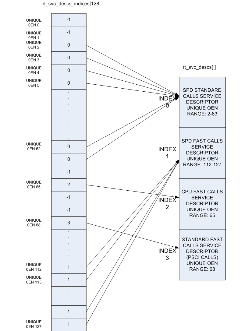
The OEN and call type fields present in the SMC Function ID cover a total of 128 distinct services, but in practice a single descriptor can cover a range of OENs, e.g. SMCs to call a Trusted OS function. To optimize the lookup of a service handler, the framework uses an array of 128 indices that map every distinct OEN/call-type combination either to one of the declared services or to indicate the service is not handled. This rt_svc_descs_indices[] array is populated for all of the OENs covered by a service after the service init() function has reported success. So a service that fails to initialize will never have it's handle() function invoked.
The following figure shows how the rt_svc_descs_indices[] index maps the SMC Function ID call type and OEN onto a specific service handler in the rt_svc_descs[] array.
Handling an SMC
When the EL3 runtime services framework receives a Secure Monitor Call, the SMC Function ID is passed in W0 from the lower exception level (as per the SMCCC). If the calling register width is AArch32, it is invalid to invoke an SMC Function which indicates the SMC64 calling convention: such calls are ignored and return the Unknown SMC Function Identifier result code 0xFFFFFFFF in R0/X0.
Bit[31] (fast/standard call) and bits[29:24] (owning entity number) of the SMC Function ID are combined to index into the rt_svc_descs_indices[] array. The resulting value might indicate a service that has no handler, in this case the framework will also report an Unknown SMC Function ID. Otherwise, the value is used as a further index into the rt_svc_descs[] array to locate the required service and handler.
The service's handle() callback is provided with five of the SMC parameters directly, the others are saved into memory for retrieval (if needed) by the handler. The handler is also provided with an opaque handle for use with the supporting library for parameter retrieval, setting return values and context manipulation; and with flags indicating the security state of the caller. The framework finally sets up the execution stack for the handler, and invokes the services handle() function.
On return from the handler the result registers are populated in X0-X3 before restoring the stack and CPU state and returning from the original SMC.
4. Power State Coordination Interface
TODO: Provide design walkthrough of PSCI implementation.
The complete PSCI API is not yet implemented. The following functions are currently implemented:
PSCI_VERSIONCPU_OFFCPU_ONCPU_SUSPENDAFFINITY_INFO
The CPU_ON, CPU_OFF and CPU_SUSPEND functions implement the warm boot path in ARM Trusted Firmware. CPU_ON and CPU_OFF have undergone testing on all the supported FVPs. CPU_SUSPEND & AFFINITY_INFO have undergone testing only on the AEM v8 Base FVP. Support for AFFINITY_INFO is still experimental. Support for CPU_SUSPEND is stable for entry into power down states. Standby states are currently not supported. PSCI_VERSION is present but completely untested in this version of the software.
Unsupported PSCI functions can be divided into ones that can return execution to the caller and ones that cannot. The following functions return with a error code as documented in the Power State Coordination Interface PDD.
MIGRATE: -1 (NOT_SUPPORTED)MIGRATE_INFO_TYPE: 2 (Trusted OS is either not present or does not require migration)MIGRATE_INFO_UP_CPU: 0 (Return value is UNDEFINED)
The following unsupported functions do not return and signal an assertion failure if invoked.
SYSTEM_OFFSYSTEM_RESET
5. Secure-EL1 Payloads and Dispatchers
On a production system that includes a Trusted OS running in Secure-EL1/EL0, the Trusted OS is coupled with a companion runtime service in the BL3-1 firmware. This service is responsible for the initialisation of the Trusted OS and all communications with it. The Trusted OS is the BL3-2 stage of the boot flow in ARM Trusted Firmware. The firmware will attempt to locate, load and execute a BL3-2 image.
ARM Trusted Firmware uses a more general term for the BL3-2 software that runs at Secure-EL1 - the Secure-EL1 Payload - as it is not always a Trusted OS.
The ARM Trusted Firmware provides a Test Secure-EL1 Payload (TSP) and a Test Secure-EL1 Payload Dispatcher (TSPD) service as an example of how a Trusted OS is supported on a production system using the Runtime Services Framework. On such a system, the Test BL3-2 image and service are replaced by the Trusted OS and its dispatcher service.
The TSP runs in Secure-EL1. It is designed to demonstrate synchronous communication with the normal-world software running in EL1/EL2. Communication is initiated by the normal-world software
-
either directly through a Fast SMC (as defined in the SMCCC)
-
or indirectly through a PSCI SMC. The PSCI implementation in turn informs the TSPD about the requested power management operation. This allows the TSP to prepare for or respond to the power state change
The TSPD service is responsible for.
-
Initializing the TSP
-
Routing requests and responses between the secure and the non-secure states during the two types of communications just described
Initializing a BL3-2 Image
The Secure-EL1 Payload Dispatcher (SPD) service is responsible for initializing the BL3-2 image. It needs access to the information passed by BL2 to BL3-1 to do so. Hence BL3-1 implements:
-
bl31_plat_get_bl32_mem_layout()to return the extents of memory available for BL3-2's use as communicated by BL2. -
bl31_get_next_image_info(uint32_t security_state)to return a reference to theel_change_infostructure corresponding to the next image which will be run in the specified security state. The SPD uses this api with the secure security state as the parameter to get entry related information about BL3-2.
In the absence of a BL3-2 image, BL3-1 passes control to the normal world bootloader image (BL3-3). When the BL3-2 image is present, it is typical that the SPD wants control to be passed to BL3-2 first and then later to BL3-3.
To do this the SPD has to register a BL3-2 initialization function during initialization of the SPD service. The BL3-2 initialization function has this prototype:
int32_t init(meminfo *bl32_meminfo);
and is registered using the bl31_register_bl32_init() function.
Trusted Firmware supports two approaches for the SPD to pass control to BL3-2 before returning through EL3 and running the non-trusted firmware (BL3-3):
-
In the BL3-2 initialization function, set up a secure context (see below for more details of CPU context support) for this CPU and use
bl31_set_next_image_type()to request that the exit frombl31_main()is to the BL3-2 entrypoint in Secure-EL1.When the BL3-2 has completed initialization at Secure-EL1, it returns to BL3-1 by issuing an SMC, using a Function ID allocated to the SPD. On receipt of this SMC, the SPD service handler should switch the CPU context from trusted to normal world and use the
bl31_set_next_image_type()andbl31_prepare_next_image_entry()functions to set up the initial return to the normal world firmware BL3-3. On return from the handler the framework will exit to EL2 and run BL3-3. -
In the BL3-2 initialization function, use an SPD-defined mechanism to invoke a 'world-switch synchronous call' to Secure-EL1 to run the BL3-2 entrypoint. NOTE: The Test SPD service included with the Trusted Firmware provides one implementation of such a mechanism.
On completion BL3-2 returns control to BL3-1 via a SMC, and on receipt the SPD service handler invokes the synchronous call return mechanism to return to the BL3-2 initialization function. On return from this function,
bl31_main()will set up the return to the normal world firmware BL3-3 and continue the boot process in the normal world.
6. Memory layout on FVP platforms
On FVP platforms, we use the Trusted ROM and Trusted SRAM to store the trusted firmware binaries. BL1 is originally sitting in the Trusted ROM. Its read-write data are relocated at the base of the Trusted SRAM at runtime. BL1 loads BL2 image near the top of the the trusted SRAM. BL2 loads BL3-1 image between BL1 and BL2. This memory layout is illustrated by the following diagram.
Trusted SRAM
+----------+ 0x04040000
|          |
|----------|
|   BL2    |
|----------|
|          |
|----------|
|   BL31   |
|----------|
|          |
|----------|
| BL1 (rw) |
+----------+ 0x04000000

Trusted ROM
+----------+ 0x04000000
| BL1 (ro) |
+----------+ 0x00000000
Each bootloader stage image layout is described by its own linker script. The linker scripts export some symbols into the program symbol table. Their values correspond to particular addresses. The trusted firmware code can refer to these symbols to figure out the image memory layout.
Linker symbols follow the following naming convention in the trusted firmware.
-
__<SECTION>_START__Start address of a given section named
<SECTION>. -
__<SECTION>_END__End address of a given section named
<SECTION>. If there is an alignment constraint on the section's end address then__<SECTION>_END__corresponds to the end address of the section's actual contents, rounded up to the right boundary. Refer to the value of__<SECTION>_UNALIGNED_END__to know the actual end address of the section's contents. -
__<SECTION>_UNALIGNED_END__End address of a given section named
<SECTION>without any padding or rounding up due to some alignment constraint. -
__<SECTION>_SIZE__Size (in bytes) of a given section named
<SECTION>. If there is an alignment constraint on the section's end address then__<SECTION>_SIZE__corresponds to the size of the section's actual contents, rounded up to the right boundary. In other words,__<SECTION>_SIZE__ = __<SECTION>_END__ - _<SECTION>_START__. Refer to the value of__<SECTION>_UNALIGNED_SIZE__to know the actual size of the section's contents. -
__<SECTION>_UNALIGNED_SIZE__Size (in bytes) of a given section named
<SECTION>without any padding or rounding up due to some alignment constraint. In other words,__<SECTION>_UNALIGNED_SIZE__ = __<SECTION>_UNALIGNED_END__ - __<SECTION>_START__.
Some of the linker symbols are mandatory as the trusted firmware code relies on them to be defined. They are listed in the following subsections. Some of them must be provided for each bootloader stage and some are specific to a given bootloader stage.
The linker scripts define some extra, optional symbols. They are not actually used by any code but they help in understanding the bootloader images' memory layout as they are easy to spot in the link map files.
Common linker symbols
Early setup code needs to know the extents of the BSS section to zero-initialise it before executing any C code. The following linker symbols are defined for this purpose:
__BSS_START__This address must be aligned on a 16-byte boundary.__BSS_SIZE__
Similarly, the coherent memory section must be zero-initialised. Also, the MMU setup code needs to know the extents of this section to set the right memory attributes for it. The following linker symbols are defined for this purpose:
__COHERENT_RAM_START__This address must be aligned on a page-size boundary.__COHERENT_RAM_END__This address must be aligned on a page-size boundary.__COHERENT_RAM_UNALIGNED_SIZE__
BL1's linker symbols
BL1's early setup code needs to know the extents of the .data section to relocate it from ROM to RAM before executing any C code. The following linker symbols are defined for this purpose:
__DATA_ROM_START__This address must be aligned on a 16-byte boundary.__DATA_RAM_START__This address must be aligned on a 16-byte boundary.__DATA_SIZE__
BL1's platform setup code needs to know the extents of its read-write data region to figure out its memory layout. The following linker symbols are defined for this purpose:
__BL1_RAM_START__This is the start address of BL1 RW data.__BL1_RAM_END__This is the end address of BL1 RW data.
BL2's and BL3-1's linker symbols
Both BL2 and BL3-1 need to know the extents of their read-only section to set the right memory attributes for this memory region in their MMU setup code. The following linker symbols are defined for this purpose:
__RO_START____RO_END__
How to choose the right base address for each bootloader stage image
The current implementation of the image loader has some limitations. It is designed to load images dynamically, at a load address chosen to minimize memory fragmentation. The chosen image location can be either at the top or the bottom of free memory. However, until this feature is fully functional, the code also contains support for loading images at a link-time fixed address.
BL1 is always loaded at address 0x0. BL2 and BL3-1 are loaded at specified locations in Trusted SRAM. The lack of dynamic image loader support means these load addresses must currently be adjusted as the code grows. The individual images must be linked against their ultimate runtime locations.
BL2 is loaded near the top of the Trusted SRAM. BL3-1 is loaded between BL1 and BL2. All three images are resident concurrently in Trusted RAM during boot so overlaps are not permitted.
The image end addresses can be determined from the link map files of the different images. These are the build/<platform>/<build-type>/bl<x>/bl<x>.map files, with <x> the stage bootloader.
bl1.maplink map file provides__BL1_RAM_END__address.bl2.maplink map file provides__BL2_END__address.bl31.maplink map file provides__BL31_END__address.
To prevent images from overlapping each other, the following constraints must be enforced:
__BL1_RAM_END__ <= BL31_BASE__BL31_END__ <= BL2_BASE__BL2_END__ <= (<Top of Trusted SRAM>)
This is illustrated by the following memory layout diagram:
+----------+ 0x04040000
|          |
|----------| __BL2_END__
|   BL2    |
|----------| BL2_BASE
|          |
|----------| __BL31_END__
|   BL31   |
|----------| BL31_BASE
|          |
|----------| __BL1_RAM_END__
| BL1 (rw) |
+----------+ 0x04000000
Overlaps are detected during image linking as follows.
Constraint 1 is enforced by BL1's linker script. If it is violated then the linker will report an error while building BL1 to indicate that it doesn't fit:
aarch64-none-elf-ld: BL31 image overlaps BL1 image.
This error means that the BL3-1 base address needs to be incremented. Ensure that the new memory layout still obeys all constraints.
Constraint 2 is enforced by BL3-1's linker script. If it is violated then the linker will report an error while building BL3-1 to indicate that it doesn't fit:
aarch64-none-elf-ld: BL31 image overlaps BL2 image.
This error can either mean that the BL3-1 base address needs to be decremented or that BL2 base address needs to be incremented. Ensure that the new memory layout still obeys all constraints.
Constraint 3 is enforced by BL2's linker script. If it is violated then the linker will report an error while building BL2 to indicate that it doesn't fit. For example:
aarch64-none-elf-ld: address 0x40400c8 of bl2.elf section `.bss' is not
within region `RAM'
This error means that the BL2 base address needs to be decremented. Ensure that the new memory layout still obeys all constraints.
Since constraint checks are scattered across linker scripts, it is required to make clean prior to building to ensure that all possible overlapping scenarios are checked.
The current implementation of the image loader can result in wasted space because of the simplified data structure used to represent the extents of free memory. For example, to load BL2 at address 0x0402D000, the resulting memory layout should be as follows:
------------ 0x04040000
|          |  <- Free space (1)
|----------|
|   BL2    |
|----------| BL2_BASE (0x0402D000)
|          |  <- Free space (2)
|----------|
|   BL1    |
------------ 0x04000000
In the current implementation, we need to specify whether BL2 is loaded at the top or bottom of the free memory. BL2 is top-loaded so in the example above, the free space (1) above BL2 is hidden, resulting in the following view of memory:
------------ 0x04040000
|          |
|          |
|   BL2    |
|----------| BL2_BASE (0x0402D000)
|          |  <- Free space (2)
|----------|
|   BL1    |
------------ 0x04000000
BL3-1 is bottom-loaded above BL1. For example, if BL3-1 is bottom-loaded at 0x0400E000, the memory layout should look like this:
------------ 0x04040000
|          |
|          |
|   BL2    |
|----------| BL2_BASE (0x0402D000)
|          |  <- Free space (2)
|          |
|----------|
|          |
|   BL31   |
|----------|  BL31_BASE (0x0400E000)
|          |  <- Free space (3)
|----------|
|   BL1    |
------------ 0x04000000
But the free space (3) between BL1 and BL3-1 is wasted, resulting in the following view:
------------ 0x04040000
|          |
|          |
|   BL2    |
|----------| BL2_BASE (0x0402D000)
|          |  <- Free space (2)
|          |
|----------|
|          |
|          |
|   BL31   | BL31_BASE (0x0400E000)
|          |
|----------|
|   BL1    |
------------ 0x04000000
7. Firmware Image Package (FIP)
Using a Firmware Image Package (FIP) allows for packing bootloader images (and potentially other payloads) into a single archive that can be loaded by the ARM Trusted Firmware from non-volatile platform storage. A driver to load images from a FIP has been added to the storage layer and allows a package to be read from supported platform storage. A tool to create Firmware Image Packages is also provided and described below.
Firmware Image Package layout
The FIP layout consists of a table of contents (ToC) followed by payload data. The ToC itself has a header followed by one or more table entries. The ToC is terminated by an end marker entry. All ToC entries describe some payload data that has been appended to the end of the binary package. With the information provided in the ToC entry the corresponding payload data can be retrieved.
------------------
| ToC Header     |
|----------------|
| ToC Entry 0    |
|----------------|
| ToC Entry 1    |
|----------------|
| ToC End Marker |
|----------------|
|                |
|     Data 0     |
|                |
|----------------|
|                |
|     Data 1     |
|                |
------------------
The ToC header and entry formats are described in the header file include/firmware_image_package.h. This file is used by both the tool and the ARM Trusted firmware.
The ToC header has the following fields: name: The name of the ToC. This is currently used to validate the header. serial_number: A non-zero number provided by the creation tool flags: Flags associated with this data. None are yet defined.
A ToC entry has the following fields: uuid: All files are referred to by a pre-defined Universally Unique IDentifier UUID . The UUIDs are defined in include/firmware_image_package. The platform translates the requested image name into the corresponding UUID when accessing the package. offset_address: The offset address at which the corresponding payload data can be found. The offset is calculated from the ToC base address. size: The size of the corresponding payload data in bytes. flags: Flags associated with this entry. Non are yet defined.
Firmware Image Package creation tool
The FIP creation tool can be used to pack specified images into a binary package that can be loaded by the ARM Trusted Firmware from platform storage. The tool currently only supports packing bootloader images. Additional image definitions can be added to the tool as required.
The tool can be found in tools/fip_create.
Loading from a Firmware Image Package (FIP)
The Firmware Image Package (FIP) driver can load images from a binary package on non-volatile platform storage. For the FVPs this is currently NOR FLASH.
Bootloader images are loaded according to the platform policy as specified in plat/<platform>/plat_io_storage.c. For the FVPs this means the platform will attempt to load images from a Firmware Image Package located at the start of NOR FLASH0.
Currently the FVP's policy only allows loading of a known set of images. The platform policy can be modified to allow additional images.
8. Code Structure
Trusted Firmware code is logically divided between the three boot loader stages mentioned in the previous sections. The code is also divided into the following categories (present as directories in the source code):
- Architecture specific. This could be AArch32 or AArch64.
- Platform specific. Choice of architecture specific code depends upon the platform.
- Common code. This is platform and architecture agnostic code.
- Library code. This code comprises of functionality commonly used by all other code.
- Stage specific. Code specific to a boot stage.
- Drivers.
- Services. EL3 runtime services, e.g. PSCI or SPD. Specific SPD services reside in the
services/spddirectory (e.g.services/spd/tspd).
Each boot loader stage uses code from one or more of the above mentioned categories. Based upon the above, the code layout looks like this:
Directory    Used by BL1?    Used by BL2?    Used by BL3-1?
bl1          Yes             No              No
bl2          No              Yes             No
bl31         No              No              Yes
arch         Yes             Yes             Yes
plat         Yes             Yes             Yes
drivers      Yes             No              Yes
common       Yes             Yes             Yes
lib          Yes             Yes             Yes
services     No              No              Yes
All assembler files have the .S extension. The linker source files for each boot stage have the extension .ld.S. These are processed by GCC to create the linker scripts which have the extension .ld.
FDTs provide a description of the hardware platform and are used by the Linux kernel at boot time. These can be found in the fdts directory.
9. References
-
Trusted Board Boot Requirements CLIENT PDD (ARM DEN 0006B-5). Available under NDA through your ARM account representative.
Copyright (c) 2013-2014, ARM Limited and Contributors. All rights reserved.